V6R VRF 50Hz
78
Midea V6R Series Service Manual
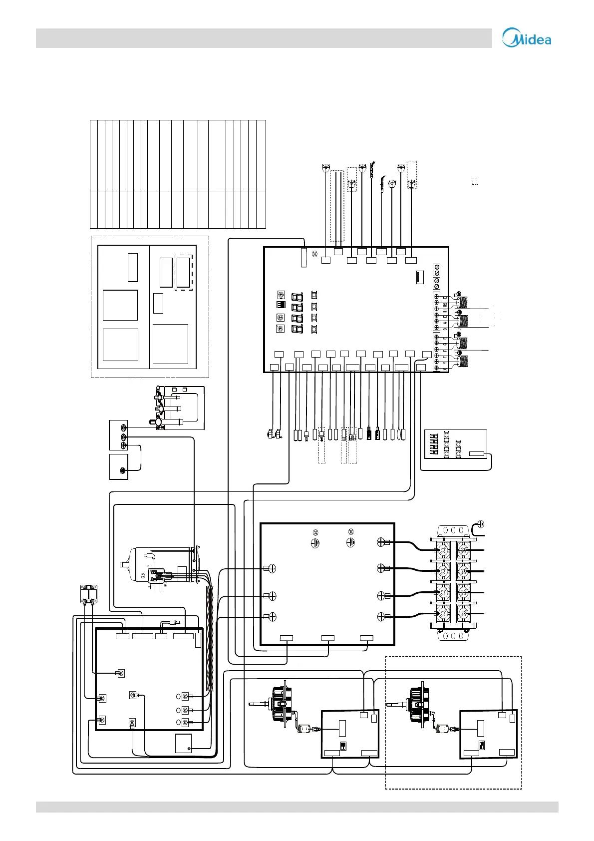
7 Wiring Diagrams
Figure5‐7.1:V6Routdoorunitwiringdiagram
DSP1 DSP2
CN7
T8 TL
EEVC
MENUDOWN
ENC3
S12
IN_NUM
H-PRO
CN72
CN12
T5
CN10
T7
CN4
T7C1
CN16
L-YL1
T8
CN19
EEVA
CN70
N-ON
CN82
CN18
T5
T7
CN17
ENC2
POWER
L3’
N
CN4
CN50
L1
L1’
L2
L2’
L3
L3’
CN3 CN2 CN1
CN8
CN7
CN6
L1 L2 L3
XT1
N
CN3
N
P
U
V W
CN5
P_out
CN1P_in
U
V
w
Brown
Black
Gray
COMP.
Black Gray
Reactor
CN16
CN7
L1
L2
CN17 CN18 CN19
1
ON
2
1
O
N
2
1
ON
2
3
XT1
Reactor
Black
DSP1 DSP2
CN1
ENC1
NUM_S
SW1
S
W
1
H-PRO
EEVC
EEVA
TL
L-PRO
L-PRO
CN14
T9
T9
CN3
TF1
TF
CN15
INV1 INV2
INV1
INV2
T7C1
H-YL1
H-YL1
L-YL1
CN26
O-C
CN27
O-FAN
CN28
CN8
T6A
CN6
T6B
CN1
T4 T3
O-D
T6A
T6B
T4
T3
UP MENU KEY
DOWN
OK
R
-
O
F
F
1
C
N
9
1
C
N
9
2
R
-
O
F
F
2
C
N
9
U
S
B
U
P
G
R
A
D
E
UP OK
C
N
3
0
L1 N L3
CN83
SV8A
CN48
SVK1
CN47
ST1
CN66
HEATA
CN66-1
HEATA
CN46
SV7
CN44
SV5
CN42
SV3/SVC
SV8A
SVK1
Brown
Brown
HEATA
HEATA
ST1
SV7
SV5
SV3/SVC
Blue
Blue
Blue
Blue
Blue
Blue
To
kilowatthour
meter
To
centralized
controller
To O D U
communication
bus
To M S o r HT
hydro module
communication
bus
Brown BlueGray
Power in
DC fan drive
board A
DC fan drive
board B
CN51
AC filter board
CN8
C
N
7
Fan A
Left
CN3
N
P
CN8
C
N
7
Fan B
Right
CN11CN41CN30
Black Brown Gray
Black
Brown
Yellow/Green
Brown
Brown
R
e
d
W
h
i
t
e
Red
White
Red
White
CN38CN8/CN9CN4/CN6
CN20
L3
CN15
Gray
CN21
H
-
P
R
O
-
1
Up layer
Down layer
PCBA Layout
Main board
AC filter
board
DC fan drive
board A
DC fan drive
board B
Compressor
drive board
CODE NAME
ST1 Four-way valve
XT1 Terminal block
H-PRO/H-PRO-1
T3
High pressure switch
XS1-XS2 Plug
XP1-XP2
Jack
T5,T9
T6A,T6B
Condenser or evaporator
temperature sensor
Outdoor ambient
temperature sensor
T4
L-YL1
H-YL1
Low pressure sensor
High pressure sensor
T7/T8/TL
SV3/SVC/SV5
SV7/SCK1/SV8A
Solenoid valve
HEATA
Crankcase heater
L-PRO
Low pressure switch
E EVA
/EEVC
Electronic expansion value
XP1
XS1
XP2
XS2
Temperature sensor
of the tube
Auxiliary
module
The wiring picture ( )shown is used by some modles.
This connection diagram is for reference onl y,please refer
to the actual product.
Main exchanger pipe temperature
sensor
T7C1 Discharge temperature sensor
COMP. Inverter compressor
FanA/Fan B DC Fan
Valve plate assembly
Main box
To p
Main box
Bottom
Ye l lo w / G r e en
Brown
CN1/CN4 CN5/CN6
CN1/CN4
CN5/CN6
C
N
2
2
C
N
2
3
Ferrite core
N=1
Ferrite core
N=1
Main board
Main box
Yellow/Green
Bottom
Alarm
Blue
CN80
Red
Alarm
Compressor
drive board
 Loading...