Do you have a question about the Midea VRF Series and is the answer not in the manual?
Details on various indoor and outdoor unit capacities and their interrelations.
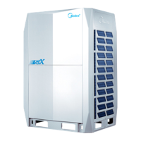
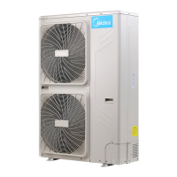
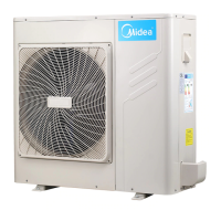
Visual representations and descriptions of different indoor and outdoor unit types.
Information on how outdoor units can be combined for different system capacities.
Guidelines and limitations for the ratio between indoor and outdoor unit capacities.
Identification and location of key internal components within the outdoor unit.
Visual representation of the refrigerant piping system for different unit configurations.
Diagrams illustrating refrigerant flow during various operating modes like cooling and heating.
A flowchart detailing the overall control strategy and activation of different control functions.
Explains the conditions and procedures for system shutdown and abnormal stops.
Describes the control mechanisms implemented when the system is in standby mode.
Outlines the sequence and controls for starting up the system, including combination modules.
Details the control logic for outdoor and indoor unit components during normal operation.
Explains various protection mechanisms to prevent system damage and ensure safe operation.
Covers special operational modes like oil return and defrosting operations.
Describes other control functions such as overload, pump-down, and noise reduction modes.
Details on PCB switches and their settings for configuring outdoor unit parameters.
Explains the switch settings for various modes on the MS box, like silent or leakage detection.
Illustrates the physical layout of components within the outdoor unit's electric control box.
Identifies and describes the ports and connections on the outdoor unit's main printed circuit board.
Details the functions and components of the data transfer module for system checks and data.
Information on the compressor inverter module, including its ports, LEDs, and specifications.
Details the ports and connections of the fan module, crucial for unit ventilation.
Describes the ports, switches, and functions of the Mode Selection Box main PCB.
Comprehensive wiring diagrams for outdoor units and MS boxes, showing all connections.
A comprehensive table listing all error codes, their descriptions, and required actions.
Step-by-step procedures for diagnosing and rectifying common outdoor unit errors and faults.
Detailed troubleshooting steps for errors related to the Mode Selection Box (MS).
Contains supplementary technical data, such as sensor resistance and pressure characteristics.
| Compressor Type | Inverter Scroll Compressor |
|---|---|
| Type | Variable Refrigerant Flow (VRF) |
| Refrigerant | R410A |
| Control | Centralized control, individual control |
| Indoor Unit Types | Wall mounted, cassette, ducted, floor standing |
| Energy Efficiency | High energy efficiency with DC inverter technology |
| Indoor Unit Noise Level | 19 dB(A) to 45 dB(A) |