Part 3
-
System Design and Installation
4.5 Mode Selection Box Selection and Piping
MS should be selected according to Table 3-4.12.
Max. number of indoor unit groups
Max. number of units per group
Max. number of downstream indoor units
Max. capacity of each group of
indoor units
Total capacity of downstream
indoor units
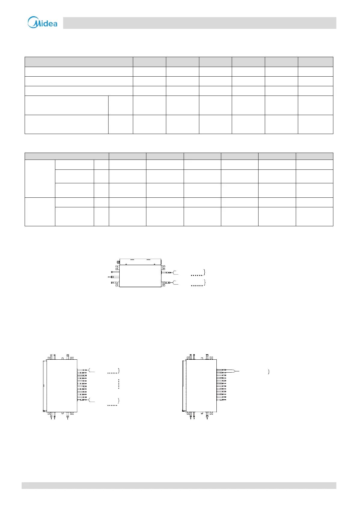
Table 3-4.13: Pipe size of MS
Figure 3-4.7: MS Connecting to indoor unit
≤
32kW
Notes:
1. If auto mode funition is required, only one indoor unit is can be connected.
2. All the indoor units connect to the same MS01 should operate the same mode to avoid mode conflict.
Figure 3-4.8: MS Connecting to indoor unit
≤
16kW
Figure 3-4.9: MS Connecting to indoor unit 16-28KW
Notes:
1. If auto mode funition is required, only one indoor unit is can be connected to one branch.
2. All the indoor units connect to the same MS branch should operate the same mode to avoid mode conflict.
3. Use optional branch pipe (Model:FQZHN-09A) and merge the two ports to one, then large capacity (16-28KW) indoor unit can be connect to MS04-
12.
4. The allowed ports merge: No.1&No.2, No.3& No.4, No.5&No.6, No.7&No.8, No.9&No.10, No.11&No.12. Other ports is not allowed to merge.
indoor unit
indoor unit
max:8 units
max:8 units
indoor unit
indoor unit
max:5 units
max:5 units
indoor unit
max: 1 unit,
max capacity:28KW
 Loading...