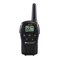
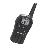
LXT110
ALIGNMENT PROCEDURE
Page 2
5. TRANSMITTER OUTPUT POWER CONFIRMATION
A. Set unit to channel 1 and power Hi mode.
B. Press & hold the PTT button.
C. Transmit power should normally be between 0.35W to 0.8W.
D. Set unit to channel 14.
E. Press & hold the PTT button. Ensure that Tx Power should be between 0.35-0.8W.
6. TRANSMITTER DEVIATION ALIGNMENT
A. Connect an audio generator (600 ohms) to the ear jack. The audio frequency should be set
at 1KHz with a level of 200mV RMS.
B. Connect an FM deviation meter (communications test set) to Antenna contact. Set the
monitor to read peak to peak divided by two [(pk-pk)/2] deviation. Set filter of equipment
from 25Hz to 15KHz.
C. Press & hold the PTT button.
D. Align RV2 for +/- 2.0 kHz deviation (+/-0.1KHz). RV2 is located on the bottom of the VCO
shield can.
E. Decrease audio generator level until deviation reads +/- 1.5 kHz (approximately 7mV) and
record generator level. Level should be between 4 mV and 10 mV.
F. Confirm that transmit audio distortion is less than 5%.
7. RECEIVER ALIGNMENT
A. Set the output level of the RF signal generator for -47dBm. The generator should be set for
1.5 kHz deviation at 1 kHz audio.
B. Set volume level 4 (It is initial.).
C. Connect Audio analyzer to SPKOUT.
D. Set equipment filter 25Hz to 15KHz.
E. Confirm that Rx Sensitivity is less than –119dBm (nominally –121dBm) by reducing the
output level of the RF signal generator until a 12 dB SINAD reading is achieved.
F. Set signal generator level to –47dBm.
G. With 1.5KHz deviation at 1KHz modulation, set volume for maximum audio. Audio level
should be on over than 1.4Vrms.
8. BATTERY INDICATOR CONFIRMATION
A. Set unit to receiving mode. Don’t set transmitter mode..
B. Set power supply voltage to 4.5V.
C. Decrease power supply voltage until low battery icon blinks.
9. POWER OFF CURRENT CONSUMPTION
A. Set power supply voltage to 6V and connect to unit.
B. Confirm current. It must be less than 300uA.
10. FREQUENCIES TABLE
Channel Freq. MHz Channel Freq. MHz

 Loading...