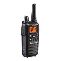
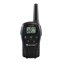
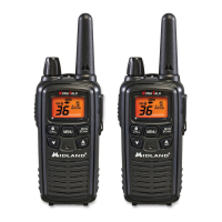
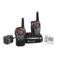
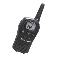
LXT110
LABORATORY TESTING PROCEDURES
Page 2
SPECIFIC TEST METHODS AND GUIDANCE
Modulation Characteristics – (paragraph 2.1047(a) of the Rules)
FOR TX AUDIO FILTER RESPONSE
1. Connect audio generator with 10uF coupling capacitor to microphone input jack.
Press PTT button.
2. Connect RF output with modulation meter. (Filters of modulation meter should be
set to a 50Hz to 15KHz.)
3. Adjust audio generator about 3-5mVrms for 0.75KHz modulation.
4. While transmitting, sweep generator and note measurement.
5. Please compensate the back-ground noise level.
Modulation Characteristics – (paragraph 2.1047(b) of the Rules
FOR TX AUDIO LOW PASS FILTER RESPONSE.
1. Connect audio generator with 10uF coupling capacitor to microphone input jack.
Press PTT button.
2. Connect AC voltmeter or other test equipment via jumper wire to TP9.
3. Adjust audio generator for 200mV.
4. While transmitting, sweep generator and note measurement.
Occupied Bandwidth – (paragraph 2.1049(c) of the Rules)
1. Connect an audio frequency sweep generator with 10uF coupling capacitor to
microphone input jack.
2. Adjust audio generator to a frequency of 2500Hz and a level of 100mV rms (+16dB
above 10-12mV per FCC).
3. With a spectrum analyzer, transmit the radio and monitor the transmitter though an
antenna.
4. Note required measuements per FCC.

 Loading...


