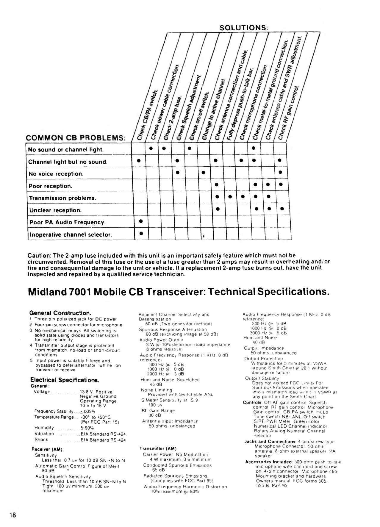
SOLUTIONS.
' I
JS
JS
rv
ß 1 i f f ß t л I Jt,
No sound or channel light.
•
•
•
• 1
Channel light but no sound.
•
•
•
• •
•
No voice réception.
•
•
•
Poor réception.
•
• • •
Transmission problems.
• • •
• •
Unclear réception.
•
• •
1 •
Poor PA Audio Frequency.
•
Inoperative channel seiector.
•
T
Caution: The 2-amp fuse included with this unit is an important safety teature which must not be
circumvented. Removal of this fuse or the use of a fuse greater than 2 amps may resuit in overheating and/or
fire and consequential damage to the unit or vehicle. If a replacement 2-amp fuse burns oui, hâve the unit
inspected and repaired by a qualified service technicien.
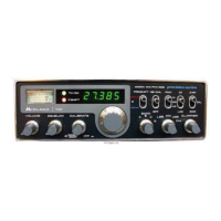
Midland 7001 Mobile CB Transceiver: Technical Spécifications.
General Construction.
1 Three-pin polanzed iack tor DC power
2 Four-pin screw connector for microphone.
3. No mechanical relays Ail switchmg is
solid state using diodes and transistors
for high reliability.
4. Transmitter output stage is protected
from mismatch, no-load or short-circuit
conditions
5. Input power is suitably filtered and
bypassed to deter alternator whme on
transmit or receive
Electrical Spécifications.
General:
Voltage
.....................
13 8 V, Positive■
Negative Ground
Operating Range:
10 V to 16 V
Frequency Stability.. .1.005%
Température Range.. -30° to + 59°C
(Per FCC Part 15)
Humidity
.................
5-90%
Vibration
.................
EIA Standard RS-424,
Shock
......................
EIA Standard RS-424
Receiver (AM):
Sensitrvity.
Less than 0 7 uv for 10 dB SN *N to N
Automatic Gain Control Figure of Merit
80 dB
Audio Squelch Sensitivity
Threshold Less than 10 cB SN*N to N.
Tighl: 100 uv minimum. 500 uv
maximum
Adjacent Channel Seiectivity and
Desensitization
60 dB (Two-generator method)
Spurious Response Attenuation
60 dB (excluding image at 50 dB)
Audio Power Output
3 W (® 10% distortion (load impédance
8 ohms résistive)
Audio Frequency Response (1 KHz 0 äB
reference)
300 Hz (в; 5 dB.
1000 Hz C* 0 dB
2000 Hz Co) -3 dB
Hum and Norse. Squelched
45 dB
Noise Limiting
Provided with Switchaßle ANL
S Meter Sensitivity at S 9
100 uv
RF Gain Range
30 dB
Antenne Input Impédance
50 ohms, unbalanced
Transmitter (AM):
Carrier Power. No Modulation
4 W maximum. 3 6 minimum
Conducled Spurious Emissions
65 dB
Radiated Spurious Emissions.
(Compiles with FCC Part 95)
Audio Frequency Harmonie Distortion
10% maximum («i 80%
Audio Frequency Response (1 KHz, 0 dB
reference)
300 Hz ę> -5 dB.
1000 Hz (S) 0 dB
3000 Hz Co; 6 dB
Hum and Noise.
40 dB
Output Impédance
50 ohms, unbalanced
Output Protection.
Withstands tor b minutes alt VSWR
around Smith Chart at 20:1 without
damage oi failure
Output Stability
Does not exceed FCC Limits For
Spurious Emissions when operated
into a mismatch load with 5 1 VSWR at
any point on the Smith Chart
Controls: Off AF gain control. Squelch
control RF gain control Microphone
Gam control. CB PA switch Hl/Lo
Tone switch NB- ANL-Off switch.
S/RF/PWR Meier Green color
Numerical LED Channel indicator
Rotary Analog-Numeral Channel
seiector
Jacks and Connections: 4-pin/screw type
Microphone Connector. 50-ohm
antenna. 8-ohm externat speaker, PA
speaker
Accessories Included: 500-ohm push to-talk
microphone with coil cord and screw-
on. 4-pin connector. Microphone clip
Mounting bracket and hardware.
Owners manuał FCC forms 505.
555-В. Part 95
 Loading...