Maintenance
Preva
99
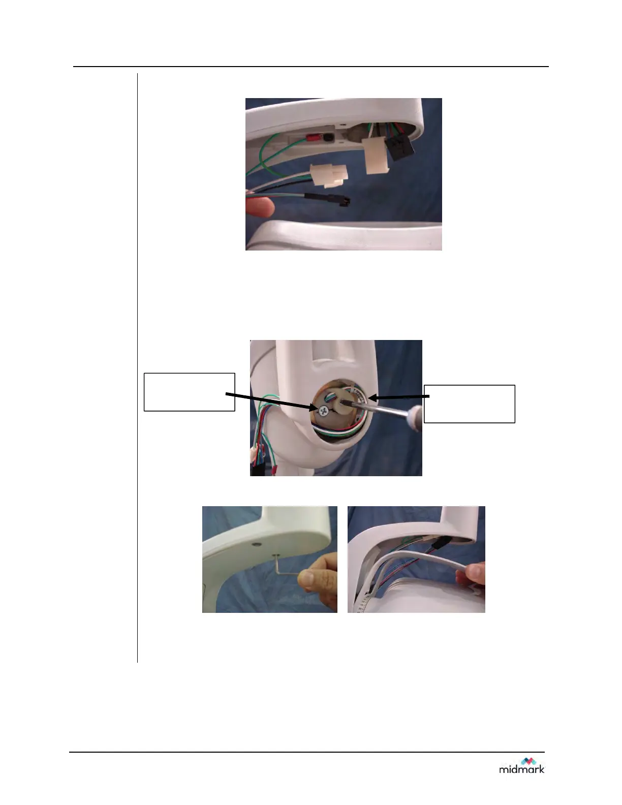
Figure 95
32. Connect the black and white connectors that were disconnected in (Step 5.)
Figure 96
33. To ensure correct operation and to prevent damage to the yoke cable
assembly perform the following steps:
33.1) Point the tubehead down.
33.2) Check that the large Phillips head screw is at the 9 o'clock position
and that there is a natural loop in the cable harness.
Figure 97
34. Mount the yoke cover that was removed in (Step 4)
35. Check to ensure the wires are not binding when you rotate the tubehead
completely clockwise or completely counter clockwise. The cabling should
expand and contract cleanly and evenly without any binding.
There should be a
natural loop in the
cable harness
Large Phillips head
screw at the 9
o'clock position