Optional Installation Procedures
Preva
55
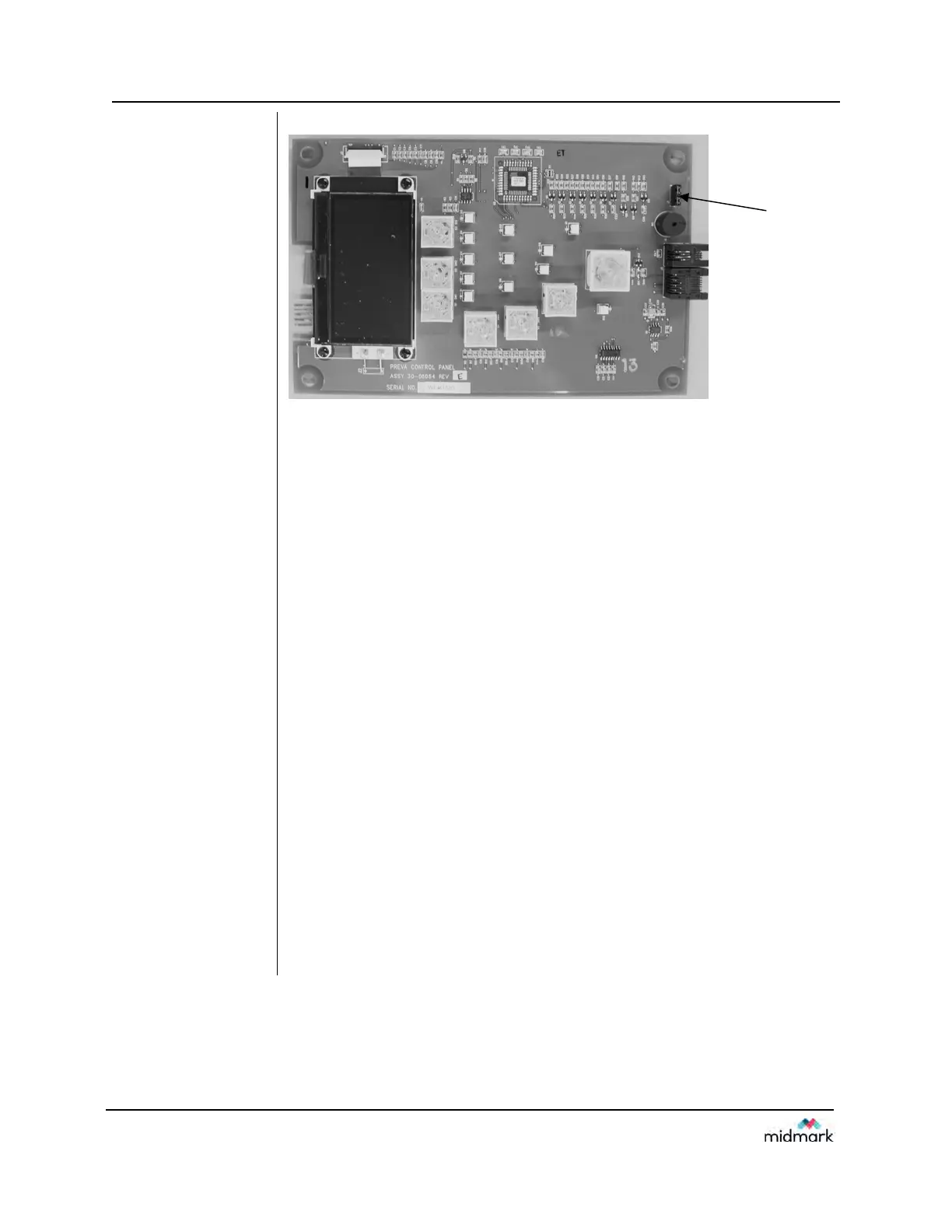
Figure 41
Disabling the Use
of the Exposure
Button
Connecting the
Coil-cord Hand
Switch—Operator
Panel Located on
Control Unit
1. Remove the screw holding the front cover of the Control Unit in place.
Place the screw in a safe location for later use.
2. Remove the front cover.
3. Cut out the notch on the base of the Control Unit front cover.
4. Route both the Operator Panel cable and the coil-cord hand switch through
the hole in the bottom of the Control Unit front cover.
5. Place a loop of the coil cord into the notch.
6. Carefully reassemble the Control Unit front cover, keeping the coil-cord in
the notch. Secure the front cover with the screw that was removed in step
1.
7. Locate the Operator Panel in the top portion of the shipping carton.
8. Connect the coil-cord hand switch to the left plug socket (as viewed from
the back) on the bottom of the Operator Panel. Connect the short white
cable to the right plug socket.
9. Carefully dress the two cables back into the front cover of the Control Unit.
10. Snap the Operator Panel into place on the front cover of the Control Unit.
11. Mount the bracket for the coil-cord hand switch in a convenient location.
12. Stow the coil-cord hand switch.
Connecting the
Coil-cord Hand
Switch—Operator
Panel in Remote
Location
1. Route the cable from the coil-cord hand switch through the hole in the wall
mounting plate.
2. Place a loop of the coil cord into the notch.
3. Locate the Operator Panel in the top portion of the shipping carton.
4. Connect the coil-cord hand switch to the left plug socket (as viewed from
the back) on the bottom of the Operator Panel. Connect the control cable
to the right plug socket.
5. Carefully dress the two cables back into the wall.
6. Snap the Operator Panel into place on the wall mounting plate.
7. Mount the bracket for the coil-cord hand switch in a convenient location.
8. Stow the coil-cord hand switch.
J7
 Loading...
