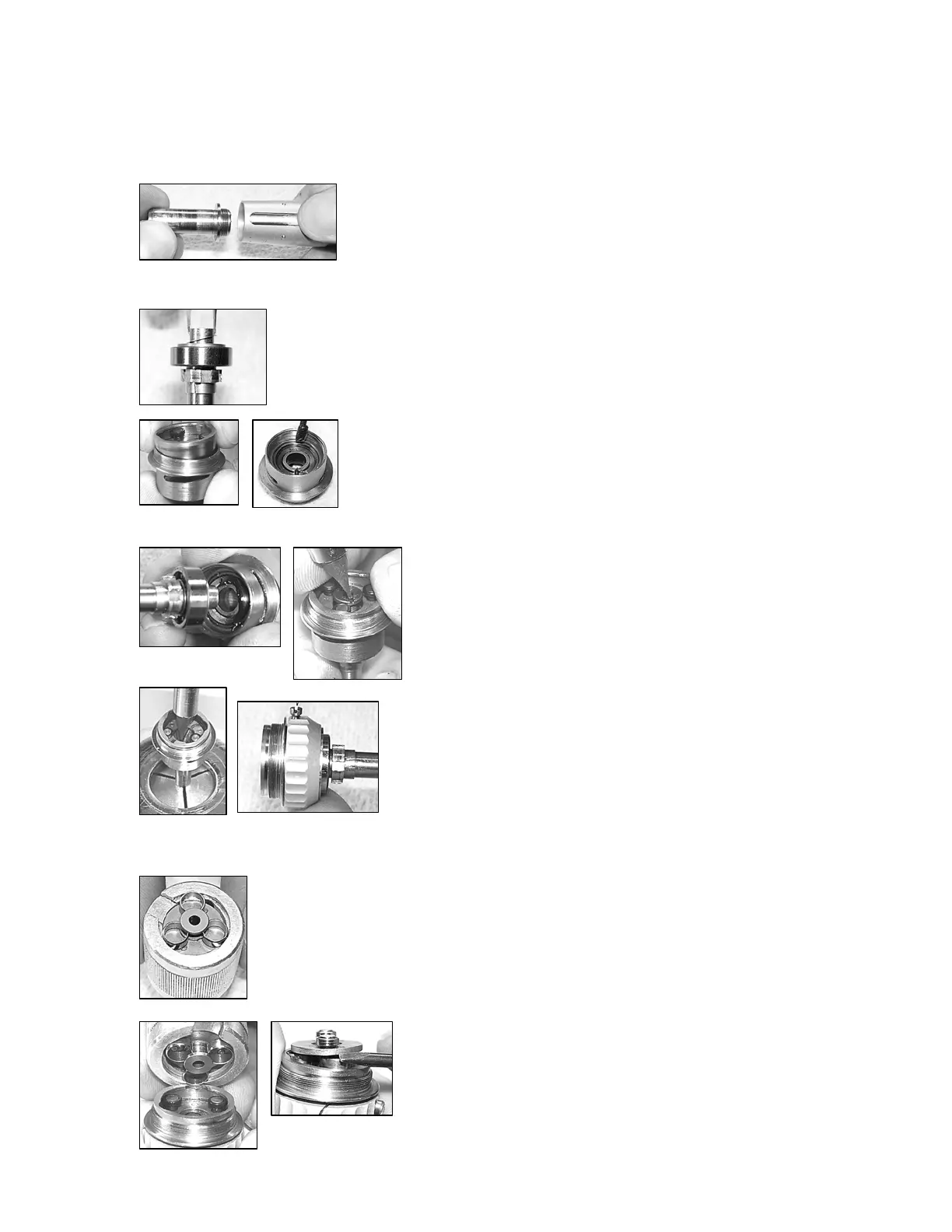
Sub Assembly A Reassembly (Nose Section)
STEP 20
Reinstall the latch kit back onto the sheath housing. Once
this is done, place the front spindle bearing into the
nosepiece. Depress the latch and screw the nosepiece back
into the housing. Firmly screw the two pieces together using two rubber strips.
STEP 21
Now place the main spindle bearing onto the back of the spindle.
Follow this by sliding the thrust washer and shim washer over the end
of the spindle.
STEP 22
Now insert the clutch into the clutch housing. Turn the
assembly over and place 2 dabs of green grease onto the
back of the clutch 180° apart from each other. This is where
you will now place the two loading springs.
STEP 23
At this point, hold the spindle assembly and clutch
assembly horizontally and opposite each other (far
left). Press them together and hold tightly while
screwing the spindle bolt into the spindle as shown
(near left).
STEP 24
Insert the spindle half way into the 3/16” collet. Now
tighten the spindle bolt, tightly, into the spindle (far left
picture). Remove from the collet. At this point you
can slip the speed change ring onto the clutch housing
and insert the screws (as shown above).
STEP 25
It is now time to install the three wide drive rings. Insert the wide drive
ring plate into your wide drive ring tool (00017). Follow that by spacing
the three drive rings evenly in the tool (as shown). Grooves are pre cut
into the tool and will properly space the wide drive rings.
STEP 26
With the drive rings properly placed in the drive ring
tool, lower it over the nose section (far left). Make
sure the three black bushings are out of the way of
the grooves where the three drive rings are to be


 To Next Page