Installation PG 8055
23.09.2016
6
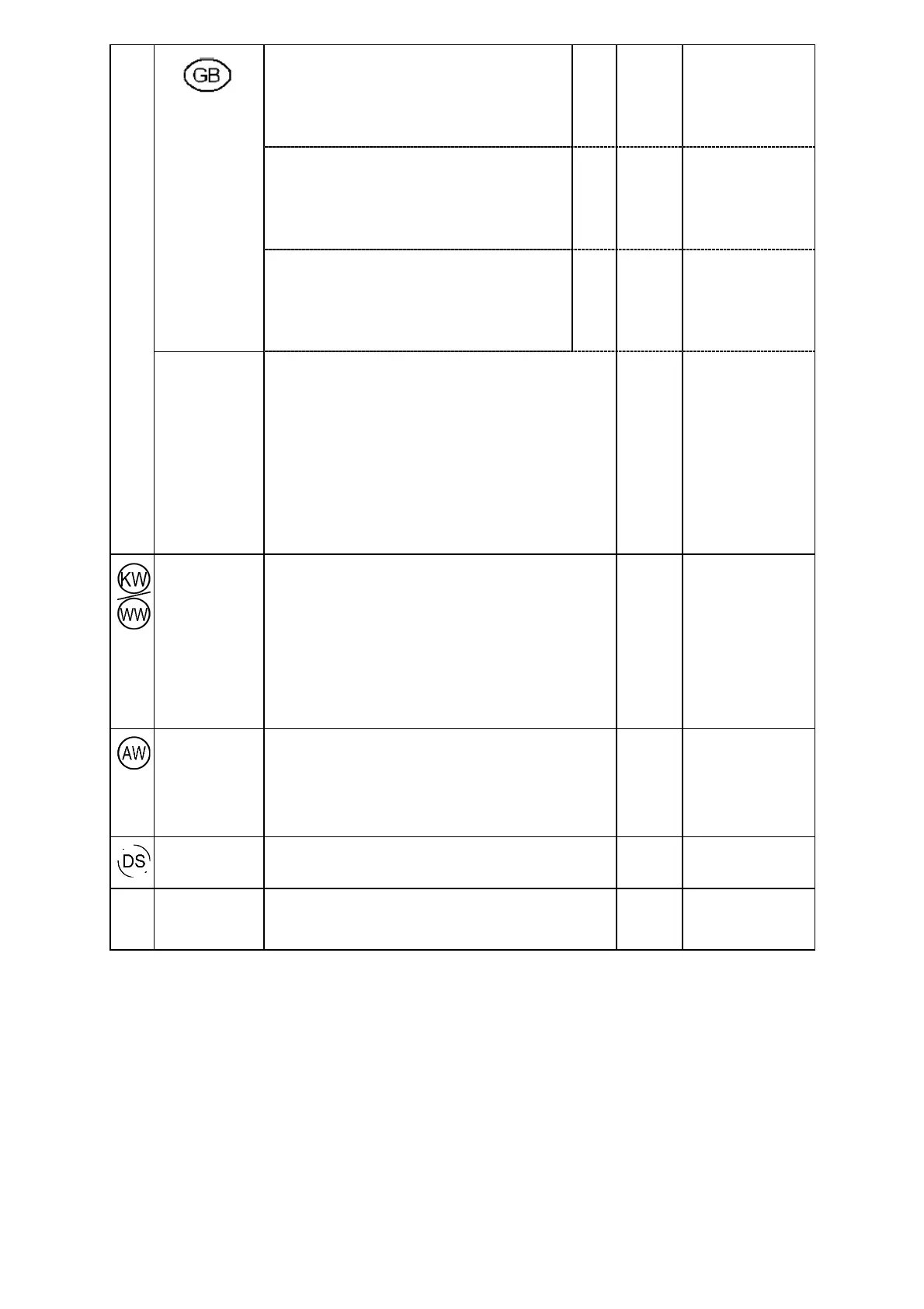
4. Voltage (standard version)
Convertible
V/Hz 3N AC 400/50
Connected load kW 8.9
Fuse rating A 3 x 15-16
Connection cable, min. gauge mm² 5 x 2.5
Connection cable length (H05(07)RN-F) without
plug
m Approx. 2.1
Voltage (standard version)
Convertible
V/Hz AC 230/50
Connected load kW 5.9
Fuse rating A 30-32
Connection cable, min. gauge mm² 3 x 4
Length of connection cable (H05(07)RN-F) with
plug
m Approx. 2.1
Voltage
Convertible
V/Hz AC 230/50
Connected load kW 3.4
Fuse rating A 13-16
Connection cable, min. gauge mm² 3 x 1.5
Length of connection cable (H05(07)RN-F) with
plug
m Approx. 2.1
It is always recommended to make electrical connection via a
plug and socket so that electrical safety checks, e.g. during
repair or service work, can be carried out easily. The socket
must be accessible after machine installation. A fixed
electrical connection is possible via an on-site main switch
providing complete isolation from the mains for all poles. The
contact gap must be at least 3 mm. In order to increase
safety, the installation of an earth leakage circuit breaker is
recommended. If necessary, equipotential bonding with good
galvanic contact must be guaranteed in compliance with all
applicable local and national installation codes.
Protection class IP 21
Cold or hot water Maximum temperature °C 65
Max. water hardness °dH 60
Minimum flow pressure kPa 200
Minimum flow pressure with extended water intake kPa 40
Maximum pressure kPa 1,000
Flow rate l/min 7.5
On-site threaded union in accordance with DIN 44991 (flat
sealing)
Inch 3/4" male thread
Length of connection hose (included) m Approx. 1.7
A double check valve must be fitted when installed in GB.
Waste water
Drain hoses (int. dia. x wall thickness) mm 22 x 6
Length of drain hose - Machine m Approx. 1.5
Max. drain hose extension m Approx. 4.0
Max. drain pump head height from base of machine m 1.0
Max. transient flow rate l/min 16
On-site hose sleeve for drain hose (outer dia. x length) mm 22 x 30
External
dispensing
(optional)
Connection of 1 dispenser for liquid detergent on rear of
machine
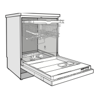
Machine feet Height-adjustable mm -0/+60
Machine foot diameter mm 35
Machine foot socket M 8