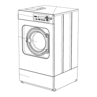
Connection for water recycling - PW 610x, PW 613x, PW 616x, PW 620x
– Disconnect the machine from the electric mains supply provided in accordance with all relevant regulations and ensure utilities
cannot be switched on again in error. Carry out a check to ensure that no power is supplied to the machine.
– Remove the screws on the left and right of the top of the lid.
– Lift the front of the lid slightly, slide it to the rear and thus release the centring cones at the rear of the lid from the connection strip.
– Remove the lid upwards.
– Remove the rear panel.
– Remove the mixer box cover plate on the rear of the machine, Fig. 1.
– Loosen the hose clip on the drain hose and disconnect the hose, Fig. 2.
– Drill out the water recycling intake on the mixer box to a diameter of approx. 28 mm, Fig. 4.
x
Warning!
Take care to collect and remove the drilling swarf at the mixer box drain outlet, Fig. 2.
– Fit the water intake hose with hose clip on the mixer box connection stub and tighten the hose clip, Fig. 6.
– Fit the mixer box cover plate with the throughfeed for the intake flange, Fig. 7.
– Refit the mixer box drain hose on the mixer box drain outlet and tighten the hose clip.
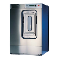
Connection for water recycling - PW 6241, PW 6321
– Disconnect the machine from the electric mains supply provided in accordance with all relevant regulations and ensure utilities
cannot be switched on again in error. Carry out a check to ensure that no power is supplied to the machine.
– Remove the machine lid.
– Remove the rear panel.
– Remove the mixer box cover plate on the rear of the machine.
– Pre-assemble the suds container / connection strip connection hose, Fig. 8.
x
Note
For the PW 6321 the hose must be shortened such that the dimension X1 = 80 mm.
– The hose to the connection strip must be shortened such that the dimension X2 = 28.5 mm, Fig. 8.
– Remove the blinding stopper on the suds container.
– To secure the holder, Fig. 8, Pos.1, drill a 6 mm hole in the suds container. Distance from rolled seam X = 110 mm, Fig. 9.
– Lay the connection hose in the machine, Fig. 10.
– Fit the angled connector and holder on the suds container, Fig. 11.
– Pass the cover plate through the opening in the connection strip and fit it.
– Fasten the connection hose with cable ties to the water intake hoses, Fig. 12.
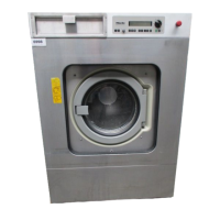
Connection for water recycling - WS 5101, WS 5141, WS 5191, WS 5240, WS 5320
– Disconnect the machine from the electric mains supply provided in accordance with all relevant regulations and ensure utilities
cannot be switched on again in error. Carry out a check to ensure that no power is supplied to the machine.
– Remove the machine lid.
– Remove the rear panel.
– Remove the mixer box cover plate on the rear of the machine.
Produktgruppe 512 Umbau- und Montageanweisung
16 von 60 M.-Nr. 04598534
16.12.2011 Diese Unterlagen dürfen ohne unsere Genehmigung weder vervielfältigt noch Dritten zugänglich gemacht werden. Eigentumsrechte vorbehalten.