10
POWER
AUX
OUT
SOLAR
INPUT
18VAC/
RCVR
GRN
BLK
RED
EXIT
SAFETY
EDGE
CYCLE
COMMON
LINK
H L
H L
+ –
ON
ALARM ACCESSORY RCVR
SEQ1
SEQ2
LEARN
BLU
ORG
WHT
GRN
R B G
CH 1 (Green Wire to Grn)
CH 1 (Blue Wire to Wht)
CH 2 (Yellow Wire to Blu)
CH 2 (Brown Wire to Grn)
RECEIVER
COM COM
CYCLE
CLOSE
SAFETY
EXIT/
OPEN
SHADOW
LOOP
CLOSE
EDGE
OPEN
EDGE
BLKGRN RED
STALL FORCE
M
I
N
M
A
X
Gate Opener Battery
RED WIRE to POSITIVE
BLACK WIRE to NEGATIVE
RED
BLACK
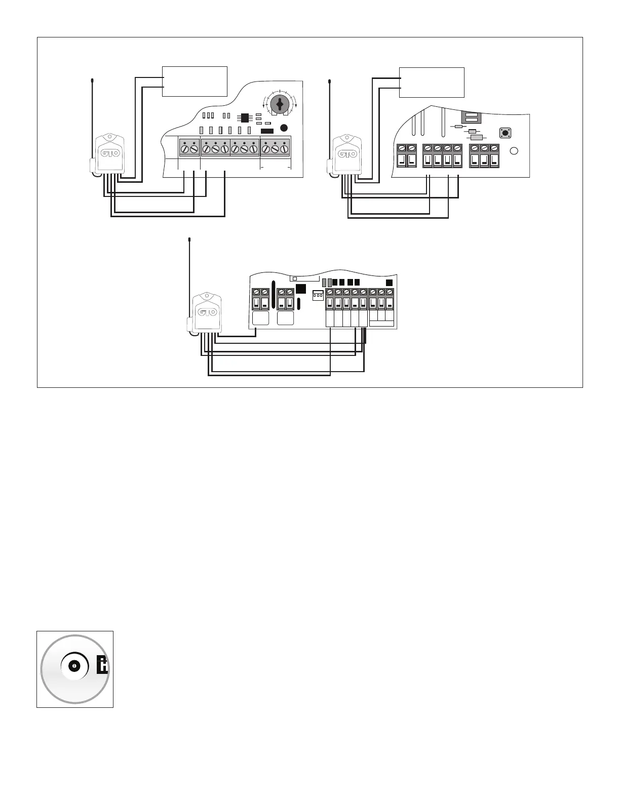
CH 1 (Green Wire to Com)
CH 1 (Blue Wire to Cycle)
CH 2 (Yellow Wire to Exit)
CH 2 (Brown Wire to Com)
RED to + or H
BLACK to Com
CH 1 (Green Wire to Com)
CH 1 (Blue Wire to Cycle)
CH 2 (Yellow Wire to Exit)
CH 2 (Brown Wire to Com)
Gate Opener Battery
RED WIRE to POSITIVE
BLACK WIRE to NEGATIVE
RED
BLACK
GREEN Control Boards
Step 5: Connect the Receiver’s Channel 2 wires (YELLOW and BROWN) to your control board (see illustration above).
Step 6: Have a helper install the 2 “AA” batteries in the Transmitter Module: this will immediately start 30 seconds of
transmission from the Wireless Vehicle Sensor. During the 30 second transmission, press and hold the Receiver’s LEARN
CH 2 button. The indicator light on the Receiver should blink twice within 1–2 seconds to indicate that the Wireless
Vehicle Sensor setting is now programmed into the Receiver.
Step 7: Proceed to “Test the System”.
5. Test the System
Step 1: Make sure gate opener is turned ON and gate is in the closed position.
Step 2: Remove and install 2 “AA” batteries (included) in the Transmitter Module; the gate will open. Wait 60 seconds
before proceeding to the next step and DO NOT move the sensor, any vehicles, or metal objects that are within 25 ft. during this
calibration/”self-test” 60-second period.
Step 3: Use your Entry Transmitter to close the gate. Test the Wireless Vehicle Sensor by driving your vehicle past the
Sensor at normal driveway speed. The gate should open each time; if it does not, use a small screwdriver to increase the
Sensitivity Adjustment (clockwise rotation).
Step 4: Once operation is satisfactory, turn the gate opener OFF. Fill the holes and trench with soil
and tamp rm. The bottom third of the Mounting Post should be buried rmly in the ground.
Step 5: Turn the gate opener ON and make sure gate is in the closed position. Replace Transmitter
Module cover and test the system again (Step 3).
NOTE: Do not cover the Transmitter Module with anything metal, as this will cause signal
interference.
Your installation is now complete. If your Wireless Vehicle Sensor is not working properly, please
refer to the Troubleshooting Guide on back cover.
GTO WIRELESS EXIT WAND
TRANSMITTER
MIN
MAX
SENSITIVITY