5
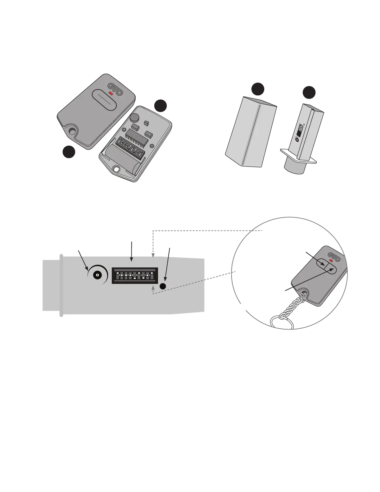
1. Program DIP Switch Settings
(This step is only for systems that are not code-safe capable.)
Step 1: Verify that your Entry Transmitter operates the gate opener.
Step 2: Remove the cover (A) from your gate opener Entry Transmitter (B). Remove the cover (C) from the Transmitter
Module (D).
Step 3: You will change the DIP Switch settings on the Transmitter Module to match those of your Entry Transmitter.
Do not change the DIP switches on the Entry Transmitter.
For Single Button Entry Transmitters, set the 9 DIP Switch settings on the Transmitter Module to match the 9 DIP Switch
settings of the Entry Transmitter.
For Dual Button Entry Transmitters, set the rst 8 DIP Switch settings on the Transmitter Module to match the 8 DIP
Switch settings of the Entry Transmitter. The 9th DIP Switch setting (Transmitter Module) will depend on which button
you use to operate the gate (see illustration above).
WIRELESS VEHICLE SENSOR
TRANSMITTER
CODE
TRANSMITTING
MIN MAX
SENSITIVITY
+
o
-
123456789
Sensitivity
Adjustment
DIP Switches
Transmit Indicator
If you use this button
to operate gate, put
the 9th DIP Switch in
the “+” position
If you use this button
to operate gate, put
the 9th DIP Switch
in the “0” position
Dual Button Entry Transmitter
Transmitter Module
1 2 3 4 5 6 7 8 9
ECE
A23S 12V
ALKALINE BATTERY
+
0
–
LED
Transmitter Module
and Cover
MIN MAX
SENSITIVITY
TRANSMITTER CODE
TRANSMITTING
1 2 3 4
C
D
Single Button Entry Transmitter and Cover
Transmitter Cover and Module
A
B