3
INTRODUCTION
A few minutes spent reading about your new MIGOMAG
MIG WELDING MACHINE will enable you to operate your
machine efficiently and benefit from its many features.
ASSSEMBLY INSTRUCTIONS
1. Fit the heavy-duty rubber tyred castor wheels and rear
wheels to the chassis of the welder. Ensure the small
lip of the cylinder tray faces the rear to enable easy
lifting of the gas cylinder.
2. Install the cable liner to the welding gun cable as
follows:
3. Lay the torch and liner out straight.
4. Check that the liner has no kinks in it.
5. Remove the liner positioning nut at the machine end
of the torch.
6. Remove nozzle, tip and nozzle holder if applicable.
7. Gently feed the liner down through the bicox cable
from the machine end of the torch, taking special care
not to kink it in the process. Once the liner reaches
the back of the swan neck it may be necessary to
gently twist it through.
8. With the liner now fully home, replace the liner
positioning nut. DON’T OVER TENSION. At the front
end of the torch there will now be approximately
300mm of liner protruding from the swan neck.
9. Gently stretch the liner a further 4mm and cut at the
tip of the neck with a sharp pair of cutters. The liner
will now spring back into the swan neck by 4mm.
10. Refit tip holder, tip and nozzle.
SETTING UP FOR OPERATION
1. Fit Torch To Machine
Carefully align gas connection tube and trigger
connection pins with central adaptor. Push in and tighten
the lock nut.
Open the wire feed pressure arm (FIG. 1) above the feed
roll.
Fit the feed roll to suit the diameter of wire to be used.
2. Feed Roll Changing (if required)
Remove the feed roll retaining knob. Pull off feed roll.
When replacing the feed roll, note the wire size which is
stamped on the face of the roll. The required size must
face inwards when the roll is re-fitted. Ensure that the
Woodruff Key is not lost.
Fit the feed roll and refit the retaining knob using thumb
and forefinger. DON’T OVER TIGHTEN.
3. Fit The Reel Of Welding Wire
Remove the red hand nut from hub.
Place the reel of wire on hub so that the wire will be drawn
off the bottom.
Ensure that the pin on the hub locates in the hole in the
side of the wire reel spool reel. Replace red hand nut.
4. Overrun Adjustment
Tighten or unscrew the hub tension nut in the centre of
the hub reel assembly unit until sufficient hub friction is
achieved to prevent overrun. This adjustment should be
done with a full spool of wire at maximum wire feed
speed. DON’T OVER TIGHTEN.
FIGURE 1.
5. Feed Roll Adjustment
Release the wire end from reel and cut off the bent wire
end, taking care that the wire does not unwind. Remove
the nozzle and contact tip from the welding gun.
Straighten about 20cm of the wire and make sure that
the end is as blunt as possible (file off if necessary). A
sharp end could damage the cable liner and the contact
tip of the welding torch. Ensure the wire is placed
correctly on to the feed rolls.
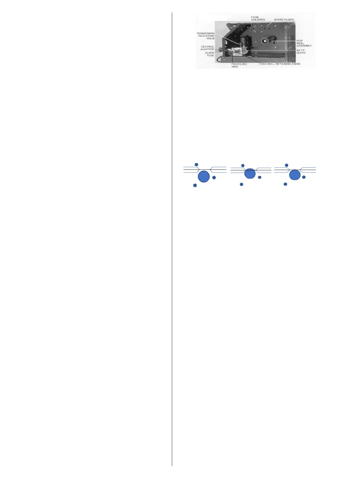
6. Feed Roll Alignment
TOO LOW TOO HIGH CORRECT
FIGURE 2.
To adjust, release the three screws holding motor drive
assembly and lower or raise to achieve correct
alignment. (FIG 2.) Thread some wire through the feed
rolls into the guide tube and liner of the welding cable.
Close the wire feed pressure arm. The pressure
adjustment of the feed rolls must be set so that the wire
is fed evenly into the liner and light restriction of the wire
can be made without the feed rolls slipping.
NOTE: Excessive pressure will cause flattening of
the wire, loosening of the wire coating and undue
wear of the rolls.
Switch on machine and set the wire feed speed dial on
a low setting. Keep the cable of the welding torch
straight and press the switch on the torch until the wire
end comes out of the gooseneck.
Replace the contact tip and nozzle.
7. Earth Connection
The earth connection from the welder should always be
made directly on to the piece to be welded. The contact
between the earth and the job should be as large and
as flat as possible and all rust and paint on the work
piece should be removed. Connect the earth cable to
the earth connection socket (5). The MIGOMAG
260AND 400 Classic have two connection sockets: (5i)
is for very light welding applications and (5ii) is for
heavier welding applications.
Fit hose tail and nut to the gas hose and hold captive
with the hose clamp, found in the wire feed
compartment of the machine adjacent to the wire feed
rolls. Connect the gas hose to the regulator, open the
cylinder valve and adjust gas flow rate. (see Shielding
Gas for flow rates).
PLUG MUST BE FITTED BY A QUALIFIED
ELECTRICIAN.
 Loading...