4
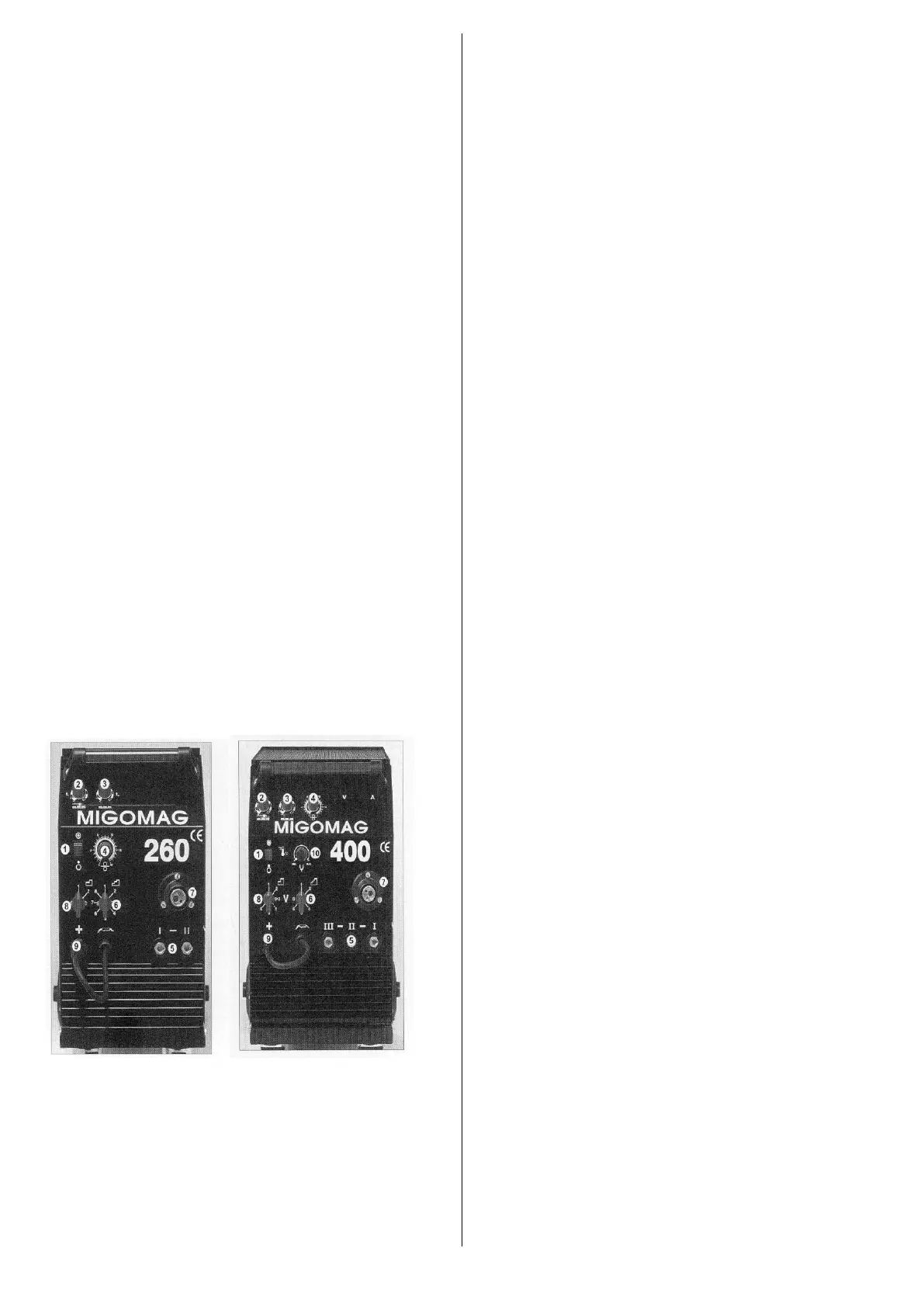
MACHINE CONTROLS
1. ON/OFF Switch
With this switch in the ON position, power is applied to
the fan and control circuits.
WARNING: THIS SWITCH DOES NOT ISOLATE THE
UNIT FROM THE MAINS ELECTRICAL SUPPLY.
2. T1 – ‘ON’ TIME CONTROL for SPOT welding and
STITCH ‘ON’ time.
3. T2 – ‘OFF TIME CONTROL for STITCH “OFF” time.
4. WIRE FEED SPEED (Current Control).
5. NEGATIVE CONNECTION
i. Inductance Socket – Low
ii. Inductance Socket – Med/High
iii. Inductance Socket – High
6. VOLTAGE SELECTOR SWITCH Fine.
7. CENTRAL ADAPTOR.
8. VOLTAGE SELECTOR SWITCH Course.
9. POSITIVE CONNECTION.
10. BURNBACK CONTROL (375)
Welding Voltage Adjustment
MIGOMAG 260
The welding voltage is regulated by a 2-position switch
for course control and a 8-position switch for fine control,
a total of 16. Position (8) and (6) on the front panel.
MIGOMAG 400
The welding voltage is regulated by a 6-position switch
for course control and a 6-position switch for fine control,
a total of 36. Position (8) and (6) on the front panel.
Warning: If the welding voltage is set too high, the
weld can burn through light guage sheet metal. In
this case the voltage should be reduced. If set too
low, the weld will have little penetration and will just
“sit on” the plate.
FIGURE 3.
Wire Feed Speed
The wire feed speed is regulated from 0-18m/min by the
potentiometer dial (4) above the voltage switch.
It is most important to select the wire feed speed in
relation to the voltage setting. The correct wire feed
speed/voltage setting is recognisable by:
1. A continuous regular ‘crackling’ sound when
welding, the characteristics of dip transfer or short-
arc welding ethod normally used by small/medium
sized MIG/MAG welders.
2. A correct shape weld bead not too high, or low, with
correct fusion along the edge of the weld without
undercut in the heat-affected zone.
Welding Mode Switch/Timer
Both ‘t1’ and ‘t2’ controls are used to control the welder
ON/OFF times during stitch welding and ‘t1’ is used
alone to control spot welding time (ON).
For normal continuous (trigger controlled) welding,
ensure both ‘t1’ and ‘t2’ controls are turned fully
anticlockwise to the OFF positions.
Protection Device
Protection against the effects of overheating is
provided by thermal protection devices mounted on the
transformer assembly.
In the event of overheating, power to the unit is
interupted.
The protection device automatically resets once the
unit cools.
SHEILDING GAS
The gas provides a shield over the weld pool to prevent
contamination from the surrounding air. The shielding
gas also contributes to arc stability, weld strength and
appearance, so care should be taken to ensure that the
correct gas type/mixture is selected for the metal being
welded. (Refer table page 10)
The gas flow rate, adjusted by the regulator, increases
with variations in welding gun diameter and should be
15 litres per minute for the MB24 welding gun to 25
litres per minute for the MB36 welding gun with
cylindrical nozzle.
Excessive gas flow rates should be avoided as they are
wasteful and, in some instances, can cause weld
porosity.
WORK ENVIRONMENT
The machine should be used indoors away from strong
draughts which may cause gas dissipation.
If the machine is to be covered, the natural cooling air
circulation must not be interrupted.
Before commencing welding, clear area of flammable
materials.
 Loading...