Do you have a question about the Mikro MK204A and is the answer not in the manual?
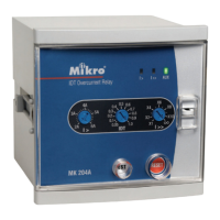
Indicates the status of the auxiliary power supply.
Shows the status of the high-set overcurrent trip function.
Shows the status of the low-set overcurrent trip function.
Adjustment for the instantaneous tripping current.
Button used to reset the relay's trip indicators.
Button for checking the relay's operational status.
Adjustment for the minimum overcurrent for tripping with time delay.
Adjustment for selecting different delay time curves.
Sets the minimum overcurrent for tripping with time delay. Range: 2A to 6A.
Sets the instantaneous tripping current. Range: 1x to 10x low-set value.
Selects delay time curves. Range: 0.05 to 1.0.
Status when AUX, I>, and I>> indicators are Off.
Status when AUX is On, and I> and I>> indicators are Off.
Status when AUX and I> indicators are On, and I>> indicator is Off.
Status when AUX is On, I> indicator blinks, and I>> indicator is Off.
Status when AUX and I>> indicators are On, and I> indicator is Off.
Status when AUX is On, I>> indicator blinks, and I> indicator is Off.
Resets the light indicators (I> or I>>) after an overcurrent tripping has occurred.
Checks relay operation by simulating overcurrent low-set and high-set trip conditions.
Tripping contacts activated during an overcurrent trip, remaining active until reset.
Wiring diagram for the MK204A overcurrent relay.
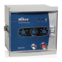
Wiring diagram for MK204A combined with MK201A relays.