MPR500 Motor Protection Relay User's Guide
Brief Overview
a
b
c
d
e
f
g
h
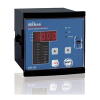
a – Run LED
b – Trip/Pickup LED
c – Thermal LED
d – Down key
e – Up key
f – Reset/Mode key
g – Test key
h – Data LED
i – Function LED
1. General Description
MPR500 is a motor protection relay that combines
thermal overload, short circuit, undercurrent, unbalance,
phase loss, phase sequence, lock/stall rotor and earth
fault protections.
MPR500 incorporates a 4-digit LED indicator which
allows direct numerical readout of set values, actual
measured value and system indication.
MPR500 has 2 relay outputs (R1 and R2). R1 is On
under normal operating condition to allow motor running,
and off during tripping. R2 is programmable to give signal
in various conditions.
A programmable binary input is provided to perform
various operations upon binary input triggering.
2. Display
2.1 Current and Thermal Capacity Display
During power up, when the relay is not under tripping
condition, the display shows current in ampere or
thermal capacity %. The Function LED indicates which
parameter is being displayed. The Data LED showing
value.
Press “UP” or “DOWN” to scroll through the parameters.
1
Motor
Protection
Relay
t
>>
I
<<
t
<<
t
6X
t
Start
I
o
>>
t
o
>>
CT
t
Stall
I
B
t
SW
I
>>
I
S
>>
i
Symbols
t
6X
– Thermal overload time constant
I>> – Short circuit/High set Overcurrent
t>> – Short circuit/High set Overcurrent
delay time
I< – Undercurrent
t< – Undercurrent delay time
– Unbalance
t – Unbalance delay time
I
0
> – Earth fault
t
0
> – Earth fault delay time
I
S
>> – Prolonged starting/stall rotor
t
Start
– Prolonged starting delay time
t
Stall
– Stall rotor delay time
I
B
– Base/full load current
CT – External current transformer ratio
SW – Soft switch
I
L1
I
L2
I
L3
I
0
Thermal
Figure 1: Front panel overview
Figure 2: Current and thermal capacity display
For current more than 1000A, a dot is shown behind
least significant digit. Eg: 1.25. = 1.25kA
I
L1
- Phase 1 current
IL2 - Phase 2 current
I
L3
- Phase 3 current
I
0
- Zero sequence/Earth fault current
Thermal % - Thermal capacity % (Thermal overload trip-
ping at 100%)
During Thermal capacity display, thermal capacity can be
cleared to 0% by pressing "UP" and "DOWN" simultane-
ously for longer than 1.5 seconds.
Warning: Clearing thermal capacity effectively reset
to cold start condition, user is not encouraged to
clear thermal capacity unless it is sure that motor is
cool enough to run/start within its thermal limit.
V1.3