2. Use provided screws to secure device to the wall;
3. Based on the wall material you can use a drill bit and provided dowels.
The device has no protection from water contamination, please ensure the placement of the device in a dry and ventilated environment.
We recommend Cat6 cables for our devices.
The mounting and configuration of this device should be done by a qualified person.
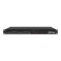
Rackmount
If desired placement is rackmount, additional brackets can be purchased separately:
RB5009 rackmount kit K-79
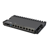
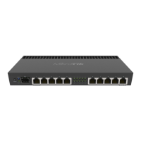
Extension slots and ports
Product code RB5009UG+S+IN
CPU 88F7040 1.4 GHz
CPU architecture ARM 64bit
CPU core count 4
Size of RAM 1 GB
RAM type DDR4
Storage 1 GB, NAND
Number of 1G Ethernet ports 7
Number of 2.5G Ethernet ports 1
Number of 10G SFP+ ports 1
USB port 1 (3.0 type A)
Operating system RouterOS (License level 5)
Switch chip model 88E6393
Dimensions 220 x 125 x 22 mm
Operating temperature -40°C to +60°C
Buttons and jumpers
The RouterBOOT reset button has the following functions. Press the button and apply the power, then:
Release the button when the green LED starts flashing, to reset RouterOS configuration to defaults.
Release the button after LED is no longer lit (~20 seconds) to cause a device to look for Netinstall servers (required for reinstalling RouterOS over the network).
Regardless of the above option used, the system will load the backup RouterBOOT loader if the button is pressed before power is applied to the device. Useful for RouterBOOT
debugging and recovery.
LED
Hidden Green LED behind the Reset button is USER LED
Blue LED 1 is the DC1 Power LED
Blue LED 2 is the DC2 Power LED
Green SFP+ LED is SFP+ port link and activity LED
Ethernet RJ45 Green LEDs are Ethernet port link and activity LEDs
Ethernet RJ45 Port 1 Orange LED is PoE-in status LED
Ethernet RJ45 Port 2-8 Orange LEDs are unused on this model
Accessories
The package includes the following accessories that come with the device:
ADAPT1_EU/US Switching Power Supply 24V 1.5A 36W
SET1_ K-55 fastening set
PAD1_ 4 pcs Pad D=7; H=1.5 mm, black, one side adhesive 3M988T
Please visit wiki pages for MikroTik SFP module compatibility table: https://wiki.mikrotik.com/wiki/MikroTik_wired_interface_compatibility
Operating system support
The device supports RouterOS software version 7.0.5. The specific factory-installed version number is indicated in the RouterOS menu /system resource. Other operating systems
have not been tested.
Federal Communication Commission Interference Statement
This equipment has been tested and found to comply with the limits for a Class B digital device, pursuant to Part 15 of the FCC Rules. These limits are designed to provide
reasonable protection against harmful interference in a residential installation.
To avoid pollution of the environment, please separate the device from household waste and dispose of it in a safe manner, such as in designated waste disposal sites.
Familiarize yourself with the procedures for the proper transportation of the equipment to the designated disposal sites in your area.

 Loading...