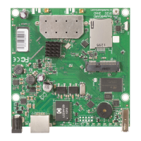
RB912UAG-series
This manual covers RouterBOARD 912UAG series models:
RB912UAG-5HPnD
RB912UAG-2HPnD
Safety Warnings
Before you work on any equipment, be aware of the hazards involved with electrical circuitry, and be familiar with standard practices for preventing
accidents.
Read the installation instructions before connecting the system to the power source.
This equipment is to be installed by trained and qualified personnel, as per these installation instructions. The installer is responsible for obtaining any
required local or national safety inspections of the structural integrity of the installation by the local authority/inspection department.
All installation methods for mounting an access point on any wall surface are subject to the acceptance of local jurisdiction.
The Installation of the equipment must comply with local and national electrical codes.
Please read the mounting instructions carefully before beginning installation.
Failure to use the correct hardware and configuration or to follow the correct procedures could result in a hazardous situation to people and damage to the
system.
We cannot guarantee that no accidents or damage will occur due to the improper use of the device. Please use this product with care and operate at your
own risk.
This is a class A device. In a domestic environment, this product might cause radio interference in which case the user might be required to take adequate
measures.
Mounting
912UAG series router for professional use. Each of the devices comes in ESD protective packaging. When handling electrical equipment please observe
the following safety precautions:
use a wrist grounding strap when unpacking and working with electrical components to avoid electrical discharge (ESD) damage,
after unpacking please place the router on the anti-static mat,
when mounting unit make sure there are no objects that can damage or touch the PCB plate,
note that ETH, USB port and DC jack are extending over the perimeter of the PCB plate.
The device can be mounted in your desired location using the factory provided four holes in a PCB plate, located on each side of the device.
Warning! This equipment should be installed and operated with a minimum distance of 380 cm between the device and your body. Operation of this
equipment in the residential environment could cause radio interference.
Connecting
1. Choose your powering solution, please see section for possibilities.Powering
2. If needed, connect accessories to the miniPCIe slot, antenna cables to the miniPCIe card and insert SIM
card.
3. Connect your ethernet cable to the gigabit ethernet port.
4. Connect your direct input power jack if not using POE, to start up the device.
5. The device will boot up and after short beep Wireless network will be available for connecting.
6. Open network connections on your pc, mobile phone or other device and search for MikroTik wireless
network and connect to it.
7. Once connected to the wireless network, open in your web browser to starthttps://192.168.88.1
configuration, since there is no password by default, you will be logged in automatically.
8. We recommend clicking the "Check for updates" button and updating your RouterOS software to the latest
version to ensure the best performance and stability.
9. Choose your country, to apply country regulation settings and set up your password in the screen that
loads.