Do you have a question about the MILACRON G Series and is the answer not in the manual?
Procedures for inspecting the unit upon delivery and handling damage.
Overview of the manual's scope, unit purpose, and model identification.
Essential safety precautions for unit operation, installation, and maintenance.
Importance of proper water quality for unit performance and longevity.
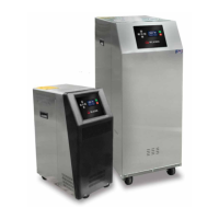
Identification of major physical parts of the temperature control unit.
General guidelines and material selection for unit installation.
How to connect the unit's process fluid inlet and outlet lines correctly.
Proper connection of the unit's water supply for efficient cooling.
Proper connection for unit draining and maintaining pressure differential.
Instructions for safe and correct electrical hookup, including voltage requirements.
Overview of the operations section and its importance for proper function.
Step-by-step guide for initial unit startup, including system fill and pump rotation.
A rapid guide to starting and operating the instrument interface.
How to navigate through the instrument's menus, screens, and buttons.
Understanding the different display screens showing unit status and functions.
Identifying and interpreting error messages displayed by the instrument.
Adjusting process temperature setpoints, deviations, and flow parameters.
Procedures for safely powering down and disconnecting the unit from its system.
Steps to diagnose and fix a unit that won't power on or display.
Steps to diagnose and fix a unit that won't start with a lit display.
Procedures for troubleshooting unexpected unit shutdowns during operation.
Identifying causes and solutions for unit overheating issues.
Troubleshooting steps for when the unit fails to reach the set temperature.
Diagnosing and resolving faults related to the AVTTM cooling valve.
Step-by-step guide for replacing the pump seal assembly.
Procedure for safely removing and replacing the unit's heater element.
Maintenance and servicing procedures for the AVTTM modulating cooling valve.
Instructions for calibrating the unit's temperature probe for accurate readings.
Detailed description of the unit's mechanical parts like pump, heater, and cylinder.
Description of the unit's electrical components, including instrument, transformer, and motors.
Visual diagrams illustrating the unit's external layout and dimensions.
Diagram showing the fluid and electrical pathways within the unit.
Explanation of how to interpret the unit's model number for configuration.
Guide to understanding readings from the unit's pressure gauges.
Instructions for operating the optional mold purge feature.
List of default configuration parameters for the unit in English units.
| Brand | MILACRON |
|---|---|
| Model | G Series |
| Category | Controller |
| Language | English |