EasyManua.ls Logo

Milescraft Design/Inlay Kit 1207 User Manual

Milescraft Design/Inlay Kit 1207
11 pages
To Next Page IconTo Next Page
Page #1 background imageLoading...
Page #1 background image
Français Modéle 1207
Avertissement de sécurité : Toujours porter des lunettes de
sécurité ou un masque facial lors de l’utilisation de l’outil. Lorsque
cet accessoire est utilisé, suivre les instructions de sécurité du
fabricant. Toujours garder les mains à l’écart des broches et outils
de coupe. Toujours débrancher l’outil avant d’installer l’accessoire.
Monter et centrer la semelle TurnLock™
Débrancher l’alimentation électrique de la défonceuse.
1
Enlever la semelle existante de la défonceuse en enlevant
les vis appropriées.
2
Insérer l’extrémité appropriée de la broche de centrage
dans le mandrin à pince. (Suivre les instructions du fabricant
de la défonceuse pour cette étape).
3
Installer la douille TurnLock fournie sur la semelle en tournant
dans l'ouverture TurnLock au centre de la semelle.
4
Placer la semelle de façon à ce que les échancrures des vis
de montage soient tournées à l’opposé de la défonceuse.
5
Après avoir baissé la semelle de façon à ce qu’elle soit en
contact avec la broche de centrage, faire tourner la semelle
sur les trous de vis filetées de la défonceuse jusqu’à ce que
l’on arrive à l’alignement correct.
Español Modelo 1207
Advertencia de seguridad: Lleve siempre gafas de seguridad o
protectores de ojos antes de empezar la operación con herramientas
eléctricas. Siga las instrucciones de su fabricante referentes a la
seguridad al usar este accesorio. Mantenga siempre las manos a
una distancia segura de los husillos y las herramientas de corte.
Desconecte siempre la fuente de alimentación antes de trabajar
con esta clase de herramientas.
Como ensamblar y centrar la placa base TurnLock™
Desconecte la rebajadora del suministro de electricidad.
1
Quite la base existente de la rebajadora desatornillando los
tornillos apropiados.
2
Inserte el extremo del perno central en el collarín de la
rebajadora. (Para este paso siga las instrucciones del
fabricante de la rebajadora).
3
Instale el cojinete TurnLock en la placa base girándolo en la
abertura del TurnLock en el centro de la placa base.
4
Coloque la placa base de modo que las concavidades para
el montaje de los tornillos queden opuestas a la rebajadora.
5
Después de bajar la placa base de modo que esté en contacto
con el perno central, rote la placa base sobre los agujeros
roscados para los tornillos de la rebajadora hasta que se
obtenga el alineamiento adecuado.
English Model 1207
Safety Warning: Always wear safety glasses or eye shields before
commencing power tool operation. Follow your manufacturer’s
instructions for safety when using this attachment. Always keep
hands at a safe distance from spindles and cutting tools. Always
disconnect power source before working with power tools.
Assembling and Centering TurnLock™ Base Plate
Remove power source from router.
1
Remove existing base from router by removing appropriate
screws.
2
Insert appropriate end of the centering pin into router
collet. (Follow your router manufacturer’s instructions for
this step.)
3
Install provided TurnLock Bushing on to the Base Plate by
twisting into the TurnLock opening in the center of Base Plate.
4
Place the Base Plate so that the screw mounting
recesses are facing away from the router.
5
After lowering the Base Plate so it is in contact with the
centering pin, rotate the Base Plate over the router’s threaded
screw holes until the correct alignment is found.
Always the Better Idea.
4
35
2
1
Assembling and Centering TurnLock™ Base Plate Monter et centrer la semelle TurnLock™ Como ensamblar y centrar la placa base TurnLock™
©2011 Milescraft • Pat. 7089978 & Other Patents Apply • www. milescraft.com 1 M1207M • RVA • 6/11
Question and Answer IconNeed help?

Do you have a question about the Milescraft Design/Inlay Kit 1207 and is the answer not in the manual?

Milescraft Design/Inlay Kit 1207 Specifications

General IconGeneral
Product TypeDesign/Inlay Kit
Model Number1207
CategoryTools
MaterialPlastic and metal
Router CompatibilityCompatible with most routers

Summary

Safety Warnings

Assembling and Centering TurnLock Base Plate

Prepare Router and Install Bushing

Disconnect power, remove old base, insert centering pin, and attach TurnLock bushing.

Align and Secure Base Plate

Position base plate, align screw holes, and rotate until correctly aligned.

Secure the Base Plate

Fasten the base plate, adjust for centering, and tighten screws to secure it properly.

Remove Centering Components

Remove the TurnLock bushing and centering pin from the router and base plate.

Assemble the Template Base

Join Template Base Halves

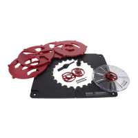
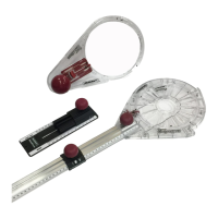
Connect the two halves of the template base by inserting tabs into the appropriate slots.

Create and Draw a Design on Paper

Select Template and Pattern

Choose a template and a pattern from the available options for your design.

Determine Rotation Interval

Identify the rotation interval from the Design Guide for positioning the template.

Rout a Design

Secure Work Surface and Template

Ensure the template base is securely fixed to the work piece surface for safe operation.

Install Router Bit and Guide Bushing

Install the appropriate router bit and guide bushing into the router for the design.

Perform Routing Operation

Guide the router along the pattern edge, rotating the template as needed to complete the design.

Create Additional Designs

Experiment with Design Variations

Vary bit depth, type, rotation interval, or bushing size to create more complex designs.

Create Cutouts or Lacework

Adjust Bit Depth for Cutouts

Set bit depth greater than material thickness and use scrap material for cutouts or lacework.

Helpful Hints

Guide Bushing and Bit Selection

Choose bushing size and router bits appropriate for intricate designs and work piece thickness.

Cutting Depth Control

Limit cutting depth per pass to 3/8-inch and use multiple passes for deeper cuts.

Creating an Inlay Pocket

Install Router Bit and Set Depth

Install 1/8" spiral bit and set cut depth slightly less than inlay material thickness.

Apply Template and Make Pass

Secure template, place 17mm bushing, and make one full pass around the template.

Clean Out Pocket

Remove excess material from within the template to create the inlay pocket.

Creating the Inlay

Set Cut Depth and Secure Material

Set depth for bit to go through inlay material and secure inlay to backing board.

Attach Template and Make Pass

Secure template to work piece, attach 11.11mm bushing, and make one pass.

Inserting the Inlay

Dry Fit and Sand if Necessary

Carefully dry fit the inlay piece into the pocket and sand if clearance issues exist.

Apply Glue and Insert Inlay

Apply a small amount of glue into the pocket and insert the inlay for a secure fit.

Product Contents

English Design Guide

Template #1 Designs

Details for Template #1 designs including window, rotation, bushing, and dimensions.

Template #2 Designs

Details for Template #2 designs including window, rotation, bushing, and dimensions.

Template #1 Lacework

Lacework patterns for Template #1 with specific settings for rotation and bushing.

Template #2 Lacework

Lacework patterns for Template #2 with specific settings for rotation and bushing.

Template #1 Cutouts

Cutout patterns for Template #1 with specific settings for rotation and bushing.

Template #2 Cutouts

Cutout patterns for Template #2 with specific settings for rotation and bushing.

French Design Guide

Gabarit #1 Designs

Motifs pour Gabarit #1 incluant fenêtre, rotation, douille et dimensions.

Gabarit #2 Designs

Motifs pour Gabarit #2 incluant fenêtre, rotation, douille et dimensions.

Gabarit #1 Lacework

Motifs de dentelle pour Gabarit #1 avec paramètres spécifiques.

Gabarit #2 Lacework

Motifs de dentelle pour Gabarit #2 avec paramètres spécifiques.

Gabarit #1 Cutouts

Motifs de découpe pour Gabarit #1 avec paramètres spécifiques.

Gabarit #2 Cutouts

Motifs de découpe pour Gabarit #2 avec paramètres spécifiques.

Spanish Design Guide

Plantilla #1 Designs

Diseños para Plantilla #1 incluyendo ventana, rotación, manguito y dimensiones.

Plantilla #2 Designs

Diseños para Plantilla #2 incluyendo ventana, rotación, manguito y dimensiones.

Plantilla #1 Lacework

Patrones de calado para Plantilla #1 con ajustes específicos.

Plantilla #2 Lacework

Patrones de calado para Plantilla #2 con ajustes específicos.

Plantilla #1 Cutouts

Patrones de recorte para Plantilla #1 con ajustes específicos.

Plantilla #2 Cutouts

Patrones de recorte para Plantilla #2 con ajustes específicos.

Router Base Plate Mounting Key

Router Compatibility Chart

Lists routers compatible with the TurnLock base plate, showing hole patterns.

Important Notes on Installation

Provides guidance on hole matching, screw usage, and modifications for proper installation.

Related product manuals