10
This completes the stab assembly
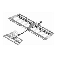
Fuselage Assembly
(not included in “short kit”)
Use the existing GWS parts from your GWS Slow
Stick™ or use the parts from our X-Fuse set.
Refer to Drawing Insert #1 for details on
fuselage assembly. Drawing 1 is scaled so that
it can be accurately measured to determine
fuselage component locations. ¼” on the
drawing will actually be 1” on the model. Wait
till the model is balanced to screw the wing
mounts and tail section in place. Refer to X-
Gear instruction sheet for assembly of X-Gear.
Temporarily mount all components including
the battery, prop, control horns and wheels.
Install linkage to ailerons and stab but leave the
stab push rods long so you can adjust the length
of the tail. Temporarily mount the wing and
stab as well. Balance the model by supporting
the model on your finger tips at the CG
location. Do NOT add weight to balance the
aircraft. Move the wing back if the model is tail
heavy or forward if it is nose heavy. Ultimately
you want the length between the wing and tail
to be maximized. More advanced pilots can
move the CG further back for more
performance. Once you have the CG set go
ahead and secure all the hardware and complete
the linkage.
Use CA glue to attach fuselage joiner to one
end of the shorter fuselage stick (tail end).
Slide one end of the longer fuselage stick into
the joiner and attach with provided screw. Cut
excess off end of screw and file down sharp
edges. See image below:
Slide the push rod guide onto the tail end of the
fuselage. Then slide the rear wing saddle
mount onto the front end of the fuselage,
approximately 15 ½” down the stick. DO
NOT SCREW IN YET.