11
Slide the two servo mounts down about an inch
from the rear wing saddle mount. Now slide
the front wing saddle mount, approximately 5
½” down from the front.
Slide the battery mount, onto the fuselage,
approximately 1” – ½” from the front. DO
NOT glue or screw in any of these plastic parts
yet, as they are in temporary positions. See
Drawing 1 for details:
Feed the long wire push rod through the push
rod guide and through the guide holes in the
rear wing saddle, so that the “Z-bend” is at the
tail section. Repeat on both sides.
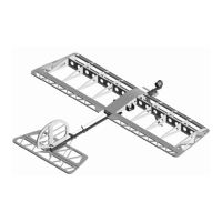
Install the servos, as per servo manufacturer
instructions, using servo manufacturer-
provided hardware. DO NOT SCREW any of
the parts in yet. See picture below:
Final Assembly
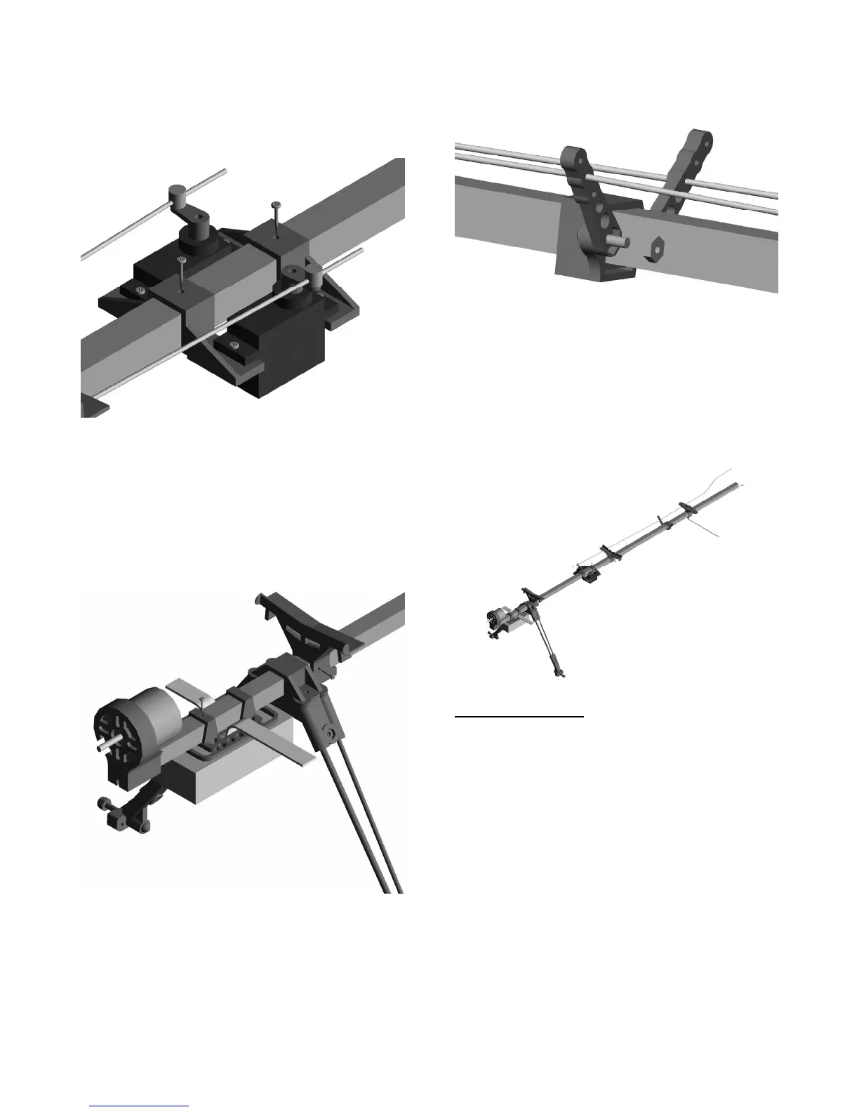
Attach the “Z-bend” end of the long control
rods into the middle hole of each one of the tail
section control horns. Feed the control rods
through the rod guides on the fuselage and then
slide the tail section on to the fuselage. See
Drawing 1 for details.
Drill two small holes on the bottom front and
center of the horizontal stabilizer. Use the #2
½” screws to fasten the fuselage to the tail
assembly. Holes should be about 3/8” from
leading edge of the horizontal stabilizer and
spaced 1” Do not damage the wood when
tightening. Use provided #2 washers. See
Drawing 1 for details.