Do you have a question about the Miller Electric CBI 801D and is the answer not in the manual?
Provides foundational safety knowledge and emphasizes learning from others' experiences.
Details essential safety practices for welding and cutting, including PPE and ventilation.
Discusses specific safety measures for arc welding, including burn protection and eye protection.
Lists relevant safety standards and their sources for further information on welding and cutting practices.
Outlines the importance of understanding the manual and unit labels for safe equipment use.
Explains the use of safety alert symbols and signal words for hazard communication.
Explains duty cycle as the percentage of operation time without causing overheating or damage.
Describes volt-ampere curves showing voltage and amperage output capabilities at different ranges.
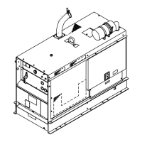
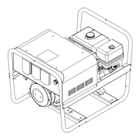
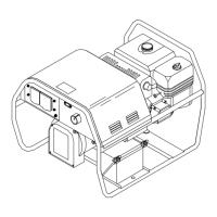
Details the unit's design as a CC DC arc welding generator with a diesel engine and auxiliary power.
Emphasizes selecting a proper site for dependable service and mentions engine exhaust gas hazards.
Provides instructions for installing an exhaust extension, warning about hot engine parts.
Details the procedure for connecting the battery, warning about acid and abnormal voltage.
Covers fuel handling precautions, refueling, and expansion space, warning about fuel spray and fire.
Explains oil level checks, oil capacity, and the function of oil pressure/temperature shutdown switches.
Describes the grounding terminal and the need to connect to a proper earth ground per codes.
Guides on selecting, preparing, and connecting weld cables for optimal output and safety.
Explains the REMOTE 9 receptacle and terminal strip for connecting remote controls and wire feeders.
Details connecting an air compressor, noting the unit provides 12 cfm at 100 psi.
Covers the installation of an optional ether starting aid, including safety warnings and procedure.
Discusses calculating load requirements for auxiliary power and limitations for motor starting.
Explains connecting 120-volt auxiliary equipment, with warnings about shock and hot surfaces.
Covers Ampere Ranges, Amperage/Voltage Adjustment, Remote Controls, and Output switch.
Details Engine Control Switch, Hour Meter, Fuel Gauge, Air Cleaner & Alternator lights.
Explains oil temp/pressure, broken belt shutdown switches, battery gauge, and meters.
Details the function and operation of the optional ether starting aid.
Step-by-step guide for performing SMAW welding, including safety and control settings.
Step-by-step guide for GMAW/FCAW, including wire feeder setup and safety.
Procedure for CAC-A, detailing setup, controls, and safety for cutting and gouging.
Instructions for operating auxiliary power, including connecting equipment and starting the engine.
Steps for operating the air compressor, involving unit setup and engine start.
Detailed pre-start checks and procedures for starting the diesel engine, including oil level.
Procedures for safely stopping all operations, auxiliary equipment, and the engine.
Outlines essential daily, hourly, and periodic maintenance tasks for the unit and engine.
Provides step-by-step instructions for cleaning or replacing the air cleaner element for engine longevity.
Details draining water from the fuel/water separator and sediment from the fuel tank.
Explains the fuel filter replacement interval and procedure, warning about fuel hazards.
Step-by-step guide for safely replacing the battery, with warnings about sparks and acid.
Covers charging procedures for maintenance-free batteries, including safety precautions.
States the governor is factory set and should not require further adjustment.
Provides instructions for adjusting engine speed if necessary, with safety warnings.
Details inspection and maintenance of brushes and slip rings for excitation voltage.
Explains the optional ether starting aid, cylinder replacement, and handling precautions.
Discusses the spark arrestor, its purpose, installation requirements, and servicing.
Guides on the proper run-in procedure for diesel engines, emphasizing load and preventing wetstacking.
Presents the detailed electrical circuit diagram for the welding generator.
Provides an exploded view and list of parts for the main assembly of the generator.
Shows an exploded view and parts list for the generator's main assembly, covering different components.
Illustrates the front panel with its various components and provides a parts list.
Shows the lower front panel with components and lists associated parts.
Details the control box components and provides a list of parts.
Illustrates the generator assembly with an exploded view and parts list.
| Brand | Miller Electric |
|---|---|
| Model | CBI 801D |
| Category | Inverter |
| Language | English |