OM-1593 Page 16
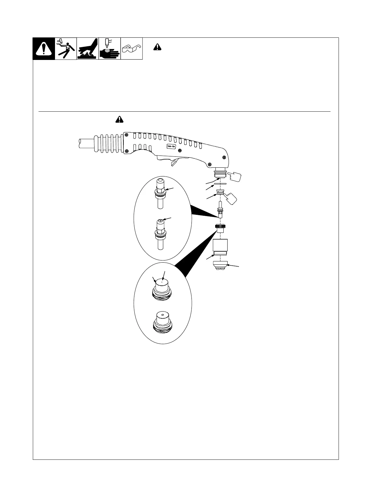
18. Checking/Replacing Retaining Cup, Tip, And Electrode For 80 Ampere (C/CM) Torch
NOTICE − Overtightening will strip threads. Do not overtighten electrode, tip,
and retaining cup during assembly. Do not cross-thread parts causing strip-
ping. Use care during torch assembly and parts replacement.
! Inspect shield cup, tip, and electrode for wear before cutting or whenever
cutting speed has been significantly reduced. Do not operate torch with-
out a tip or electrode in place. Be sure to use genuine replacement parts.
. A good practice is to replace both the tip and electrode at the same time.
803 612-A
Turn Off power source.
1 Drag Shield
2 Retaining Cup
Remove retaining cup. Check retaining cup
for cracks, and replace if necessary.
3Tip
4 Opening
Remove tip. Check tip, and replace if open-
ing is deformed or 50% oversize. If inside of
tip is not clean and bright, clean with steel
wool. Be sure to remove any pieces of steel
wool afterwards.
5 Electrode
Check electrode. If center has a pit more
than a 1/16 in (2 mm) deep, remove and re-
place electrode.
6 Swirl Ring
Remove swirl ring. Check ring, and replace
if side holes are plugged.
7 O-Ring
Check O-rings on torch. If needed, coat with
thin film of silicone lubricant (part no.
169 231). Replace if damaged.
8 Torch Head
Check this area for any debris or foreign ma-
terial. Clean out if necessary.
Carefully reassemble parts in reverse order.
6
Make sure this area is clean of
any debris.
New
Worn
New
Worn
2
5
4
3
7
8
Make sure swirl ring is clean of
any debris and no holes are
obstructed.
! Turn Off power source before checking torch parts.
1
80 ampere model requires
electrode wrench 189 086
*1/32 in (1 mm) — 1/16 in (2 mm)
maximum pit depth depending on
acceptable cut quality.
*Pit
Depth
 Loading...