Do you have a question about the Miller XR-AlumaFeed Suitcase and is the answer not in the manual?
| Brand | Miller |
|---|---|
| Model | XR-AlumaFeed Suitcase |
| Category | Wire Feeders |
| Language | English |
Explains symbols used in the manual.
Discusses various hazards related to arc welding.
Covers hazards related to installation, operation, and maintenance.
Warning about chemicals in the product.
Lists relevant safety standards.
Discusses electromagnetic field information.
Explains additional safety symbols.
Defines various miscellaneous symbols.
Location of serial number and rating label.
Information on software licensing.
Details on default weld parameters.
Provides technical specifications of the unit.
Table for wire types, sizes, and feed speeds.
Covers IP rating and temperature specs.
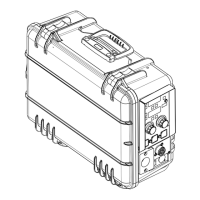
Guidance on choosing a suitable location for the unit.
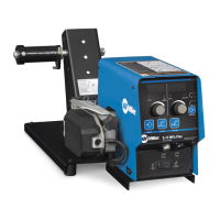
Instructions for setting up the XR-AlumaFeed.
Instructions for setting up the XR-AlumaPro gun.
Instructions for setting up the XR-Pistol Grip Gun.
Details on setting drive roll tension.
Describes power source connections.
Instructions for connecting air-cooled feeders.
Instructions for connecting air-cooled guns.
Details about the 14-pin plug.
Steps for installing a wire spool.
Instructions for threading welding wire.
Overview of the control panel and its components.
Further details on controls and setup menu operation.
Instructions for MIG welding operation.
Instructions for Non-Synergic Pulsed MIG operation.
Instructions for Synergic Pulsed MIG operation.
Definitions of operational terms used in the manual.
Explanation of jog and purge functions.
A guide for quick setup of welding parameters.
Describes how to access and navigate the setup menu.
Details on the second level of the setup menu.
How to configure the start sequence for synergic pulse.
How to configure the start sequence for non-synergic pulse or MIG.
How to configure crater fill for synergic pulse.
How to configure crater fill for non-synergic pulse or MIG.
Optimizes aluminum weld bead appearance.
Steps to reset the unit to factory defaults.
Maintenance procedures for the feeder drive assembly.
Instructions for replacing the hub assembly.
Explains error messages and diagnostic codes.
Provides solutions for common welding problems.
Provides the circuit diagram for the wire feeder.