EasyManua.ls Logo

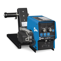
Miller Intellx Pro User Manual

Miller Intellx Pro
52 pages
To Next Page IconTo Next Page
Page #1 background imageLoading...
Page #1 background image
File: MIG (GMAW)
Processes
OM-279248C 202005
Intellx Pro
Wire Feeder
Processes
Description
Wire Feeder
MIG (GMAW) Welding
Pulsed MIG (GMAW-P)
Flux Cored (FCAW) Welding
For product information,
Owner’s Manual translations,
and more, visit
www.MillerWelds.com

Table of Contents

Questions and Answers:

Miller Intellx Pro Specifications

General IconGeneral
BrandMiller
ModelIntellx Pro
CategoryWire Feeders
LanguageEnglish

Summary

From Miller To You

Miller's Philosophy and Manual Introduction

Miller's quality message and the manual's purpose, including ISO 9001 certification.

Safety Precautions

Hazard Symbols and Electrical Safety

Explains hazard symbols and risks like electric shock, hot parts, and moving parts.

Welding Environment Hazards

Covers risks from fumes, gases, fire, arc rays, flying metal, gas buildup, EMF, and noise.

Cylinder, Installation, and Operation Risks

Discusses cylinder safety, installation hazards, and operational risks like sparks, ESD, and batteries.

Interference, Regulations, and EMF

Covers RF interference, California Prop 65, safety standards, and EMF information.

Definitions

Safety Symbols Definitions

Explains various safety symbols including warnings, disposal, and electrical precautions.

More Safety Symbols and Notes

Continues defining safety symbols for fire, eye protection, and training requirements.

Operational Symbols Definitions

Defines operational symbols for parameters like Amperes, Volts, Wire Diameter, and Arc Control.

Specifications

Product Identification and Specifications

Covers serial number, software, general specs, environmental ratings, and duty cycle.

Installation

Site Selection and Cable Management

Guides on location, airflow, movement, and arranging cables to reduce inductance.

Electrical Connections and Diagram

Details connecting weld output cables and presents the system connection diagram.

Control and Gas Connections

Explains connecting control cables and the shielding gas supply.

Voltage Sense and Drive Assembly Setup

Covers optional voltage sense connection and rotating the drive assembly.

Welding Gun and Wire Guide Installation

Details installing the welding gun, wire guides, and drive rolls.

Threading Welding Wire and Performance Tips

Guides threading wire and provides tips for optimal feeding performance.

Operation

User Interface and Control Descriptions

Introduces the wire feeder's interface, controls, and displays.

Front Panel Controls Explained

Provides detailed descriptions of each button, knob, and indicator on the front panel.

Power Switch and Jog/Purge Functions

Explains the operation of the power switch and the Jog/Purge control.

Arc Control, Memory, and Trigger Hold

Details adjusting arc characteristics, using memory settings, and the trigger hold function.

Trigger Select and Gas Timing Controls

Covers trigger select functionality and controls for preflow and postflow gas timing.

Operational Terms and Definitions

Defines key operational terms like Arc Length, EZ-Set, and Accu-Pulse.

Selecting Welding Arc and Wire Type

Guides the user through selecting the welding arc and wire type.

Selecting Wire Size, Gas, and Saving Parameters

Details selecting wire size, gas, and saving the chosen parameters.

Wire and Gas Selection Tables

Provides reference tables for compatible MIG and Accu-Pulse wire and gas combinations.

Accu-Power Feature Explanation

Explains the Accu-Power feature for displaying and calculating weld heat input.

Maintenance and Troubleshooting

Routine Maintenance Schedule

Outlines regular maintenance tasks and their frequency for equipment upkeep.

Shielding Gas Filter Fitting Cleaning

Provides specific instructions for cleaning debris from the gas filter fitting.

Troubleshooting Fault Codes

A diagnostic table listing fault codes and their descriptions for troubleshooting.

General Troubleshooting Guide

A guide to resolving common operational issues and their remedies.

Electrical Diagram

Circuit Diagram

Presents the main electrical circuit diagram for the unit.

Circuit Diagram Details

Continues the electrical circuit diagram, showing component connections.

Parts List

Main Assembly Diagram

A visual breakdown of the main assembly with numbered parts.

Main Assembly Parts Description

Lists and describes the parts for the main assembly.

Control Box Diagram

A diagram illustrating the components within the control box.

Control Box Parts Description

Lists and describes the individual parts of the control box.

Drive Assembly Diagram

A diagram showing the drive assembly components.

Drive Assembly Parts Description

Lists and describes the parts for the drive assembly.

Drive Roll and Wire Guide Kits

A table detailing drive roll and wire guide kit part numbers and types.

Warranty Information

Limited Warranty Details and Exclusions

Outlines the terms, coverage, and duration of the limited warranty.

Warranty Claim Procedures

Details the process for submitting warranty claims.

Owner's Record and Service

Owner's Record Keeping

Section for users to record purchase details and product information.

Service and Support Information

Provides contact info for distributors, service agencies, and technical support.

Related product manuals