MOUNTING
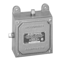
The MD-2000A speed sensor is usually coupled to the tail pulley shaft of a weighfeeder. On low speed
conveyers, the speed sensor may be coupled to the tail, bend or snub pulley. The mounting arrangement
requires the input shaft and bearing assembly to bear the weight of the speed sensor. The unit’s arresting
bracket stops the speed sensor from rotating with the shaft.
When mounting the speed sensor, ensure that the shaft alignment is true to avoid stresses on the shaft
bearing. Refer to ( MD - 2000A Series Pulley Mounting ).
INTERCONNECTION
ALL WIRING MUST BE DONE IN CONJUNCTION WITH APPROVED
CONDUIT, BOXES AND FITTINGS AND TO PROCEDURES IN
ACCORDANCE WITH ALL GOVERNING REGULATIONS.
Interconnection between the speed sensor and the integrator should be made with 3 wire shielded, 18 AWG
cable (Belden 8770 or equivalent).
Ground the shield at the integrator ONLY!
FLEXIBLE CONDUIT IS RECOMMENDED SO EXCESS STRESS IS NOT
APPLIED TO THE SHAFT BEARINGS.
SPEED SENSOR INTERCONNECTION
Terminal positions in brackets denote that only one signal may be connected at one time. To determine
direction of rotation refer to ( MD - 2000A Series Pulley Mounting ).
‘ N/C ’ denotes ‘ no connection ’
MD-2000A BW100 BW500 COMPUSCALE III
DESCRIPTION TERMINAL TO 1TB
+15 V DC(Red) 1 8 19 30
speed out-CW
(White)
2 (7) (16) (31)
speed out-CCW
(Blue)
3 (7) (16) (31)
Common
(Black)
4 6 17 32
Ground 5 N\C N\C N\C
PL-361 2

 Loading...