Home
Milnor
Washer
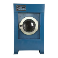
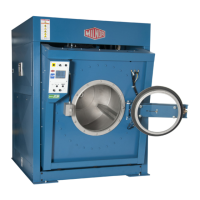
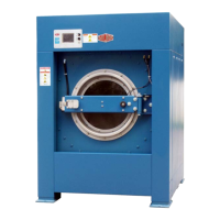
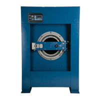
MWF100J7
Milnor MWF100J7 Maintenance Guide
4
of 1
of 1 rating
42 pages
Give review
Manual
Specs
To Next Page
To Next Page
Loading...
Published Manual Number/ECN: MKWM3H01U1/2022346A
• Publishing System: TPAS2
• Access date: 08/19/2022
• Document ECNs: Latest
MWF100J7, MWF100Z7,
MWF125J7, MWF125Z7
PELLERIN MILNOR CORPORATION
POST OFFICE BOX 400, KENNER, LOUISIANA 70063-0400, U.S.A.
2
Table of Contents
Table of Contents
8
Machine Description and Identification
11
About this Manual and Your Milnor® Machine
11
Description
11
Machine Identification
11
Machine Data Plate
11
Figure 1 Machine Data Plate
11
Safety
12
Safety - Suspended Washer Extractors
12
Safety Alert Messages-Internal Electrical and Mechanical Hazards
12
Safety Alert Messages-Cylinder and Processing Hazards
12
Safety Alert Messages-Unsafe Conditions
14
Damage and Malfunction Hazards
14
Hazards Resulting from Inoperative Safety Devices
14
Hazards Resulting from Damaged Mechanical Devices
14
Careless Use Hazards
15
Careless Operation Hazards-Vital Information for Operator Personnel (See also Operator Hazards Throughout Manual)
15
Careless Servicing Hazards-Vital Information for Service Personnel (See also Service Hazards Throughout Manuals)
15
Prevent Damage from Chemical Supplies and Chemical Systems
16
How Chemical Supplies Can Cause Damage
16
Dangerous Chemical Supplies and Wash Formulas
16
Incorrect Configuration or Connection of Equipment
17
Figure 2 Incorrect Configurations that Let the Chemical Supply Go in the Ma
18
Equipment and Procedures that Can Prevent Damage
19
Use the Chemical Manifold Supplied
19
Figure 3 Incorrect Configurations that Let the Chemical Supply Go in the Ma
19
Figure 4 Examples of Manifolds for Chemical Tubes. Your Equipment Can Look
19
Close the Line
20
Do Not Let a Vacuum Occur
20
Flush the Chemical Tube with Water
20
Put the Chemical Tube Fully below the Inlet
20
Prevent Leaks
20
Figure 5 a Configuration that Prevents Flow in the Machine When the Pump Is off (if the Chemical Tube and Tank Have no Pressure)
20
Routine Maintenance
21
Maintenance Summary
21
Guards and Related Components
22
Filters, Screens, and Sensitive Components
22
Table 1 Guards and Related Components
22
Table 2 Filters, Screens, and Sensitive Components
22
Fluid Containers
23
Components that Become Worn
23
Bearings and Bushings
23
Table 3 Fluid Containers
23
Table 4 Components that Become Worn
23
Motor Grease Schedule
24
Mechanisms and Settings
24
Table 5 Bearings and Bushings
24
Table 6 Motor Grease Schedule
24
Table 7 Mechanisms and Settings
24
How to Remove Contamination
25
Table 8 Contamination Types, Cleaning Agents, and Procedures
25
Lubricant Identification
26
Table 9 Lubricant Identification
26
Grease Gun Procedures
27
Procedures for Bearing Components Connected to a Grease Plate
27
Procedures for Motors
28
Figure 6 Motor Grease Maintenance Conditions
29
How to Show the Maintenance on a Calendar
30
Table 10 Motor Grease Intervals and Quantities
30
Maintenance Components-Machines and Controls Group
31
How to Examine V-Belts and Pulleys
31
Figure 7 Belt and Pulley Conditions to Look for
31
Table 11 Where to Put Marks on a Calendar
31
Figure 8 How to Adjust Belt Tension on a Machine that Uses Spring Tension
32
Inverters
33
Chemical Devices
33
Figure 9 Electric Box and Inverter. These Are Examples. Your Machine Can Look
33
Water and Steam Devices
34
Figure 10 Chemical Inlet Manifolds for Chemical Pump Systems. See Caution
34
Figure 11 Soap Chute and Optional 5-Compartment Supply Injector. These Are Ex
34
How to Examine Compressed Air Mechanisms
35
Figure 12 Water Pressure Regulator for Chemical Flush. These Are Examples
35
Your Machine Can Look Different
35
Figure 13 Steam Inlet Strainer. These Are Examples. Your Machine Can Look Different
35
Figure 14 Compressed Air Inlet Strainers. These Are Examples. Your Machine Can Look Different
36
Figure 15. Self-Purging Air Line Filter to Remove Moisture and Other Contamination. These Are Examples. Your Machine Can Look Different
36
Figure 16 Compressed Air Mechanisms These Are Examples. Your Machine Can Look Different
37
Photoeyes and Proximity Switches
38
How to Do a Test of Emergency Stop Mechanisms
38
Figure 17 Speed Sensor (Photoeye) on some Machines
38
Maintenance Components-Large Extractors
39
Lubricant Maintenance for Grease-Filled Drive Bearings
39
Figure 18 Grease Ports for Grease-Only Bearing Assembly
39
Lubricant Maintenance for Non-Drive Components
40
How to Do a Test of the Mechanical Brake
40
Figure 19 Grease Ports for Door-Open Pocket Models. These Are Examples
40
Your Machine Can Look Different
40
About the Shock Absorbers
41
Figure 20 Example of Disk Brake. Your Machine Can Look Different
41
Other manuals for Milnor MWF100J7
Installation And Service
110 pages
4
Based on 1 rating
Ask a question
Give review
Questions and Answers:
Need help?
Do you have a question about the Milnor MWF100J7 and is the answer not in the manual?
Ask a question
Milnor MWF100J7 Specifications
General
Model
MWF100J7
Category
Washer
Washer Type
Front Load
Capacity
100 lbs
Phase
3
Frequency
60 Hz
Motor Type
Inverter Driven
Related product manuals
Milnor MWF27J8
110 pages
Milnor MWF45J8
110 pages
Milnor MWF77J7
110 pages
Milnor MWF63C7
165 pages
Milnor MWF63J7
110 pages
Milnor MWF36J8
110 pages
Milnor MWF C Series
49 pages
Milnor MWF63C Series
117 pages
Milnor MWR12X5
111 pages
Milnor MWR18E4 Series
67 pages
Milnor MWR09E5 Series
67 pages
Milnor MilTouch 30022V8Z
34 pages