5
WARNING 7RUHGXFHWKHULVNRILQMXU\
DOZD\VKROGVHFXUHO\
&OXWFK
6HWWLQJ
$SSOLFDWLRQV
1-5
6-10
11-15
16-20
21-24
3.2-4.4
Small screws in softwood.
Medium screws in softwood or small
screws in hardwood.
Large screws in softwoods. Medium
screws in hardwood or large screws in
hardwood with pilot hole.
127( Because the settings shown in the table are only
a guide, use a piece of scrap material to test the different
clutch settings before driving screws into the workpiece.
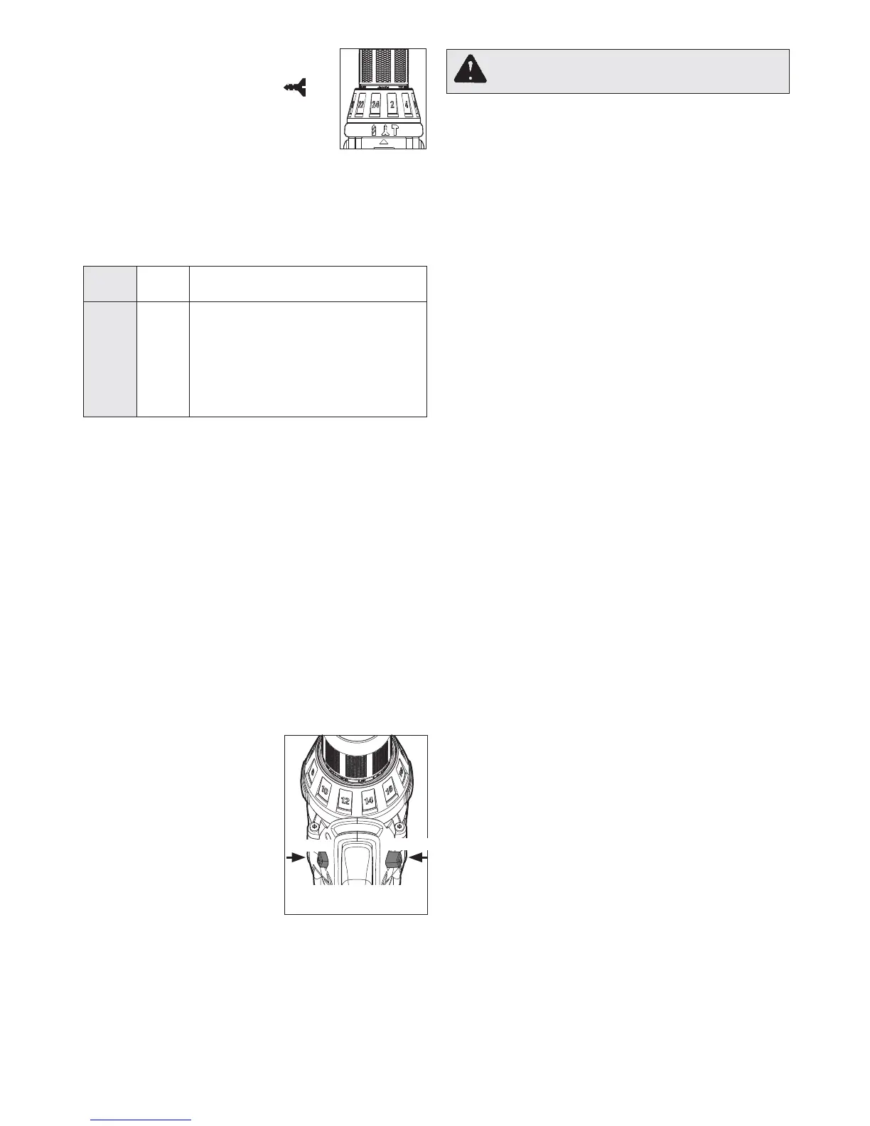
6HOHFWLQJ6SHHG
The speed selector is on top of the motor housing.
Allow the tool to come to a complete stop before
changing speeds. See “Applications” for recom-
mended speeds under various conditions.
1. For /RZ speed, push the speed selector to
display “1”.
2. For +LJK speed, push the speed selector to
display “2”.
8VLQJWKH&RQWURO6ZLWFK
The control switch may be set to three positions:
forward, reverse and lock. Due to a lockout mecha-
nism, the control switch can only be adjusted when
the ON/OFF switch is not pressed. Always allow
the motor to come to a complete stop before using
the control switch.
For IRUZDUG (clockwise)
rotation, push in the control
switch from the right side of
the tool. &KHFNWKHGLUHFWLRQ
RIURWDWLRQEHIRUHXVH
For UHYHUVH (counterclock-
wise) rotation, push in the
control switch from the left
side of the tool. &KHFNGLUHF-
WLRQRIURWDWLRQEHIRUHXVH
ToORFN the trigger, push the
control switch to the center
position. The trigger will not work while the control
switch is in the center locked position. Always
lock the trigger or remove the battery pack before
performing maintenance, changing accessories,
storing the tool and any time the tool is not in use.
3. 7RXVHWKHGULYLQJVFUHZVPRGH
rotate the application selector col-
lar until the drive symbol
0.5-2.8
Nm
ap-
pears in line with the arrow. Then
rotate the torque selector collar
until the desired clutch setting ap-
pears in line with the arrow.
The adjustable clutch, when properly adjusted,
will slip at a preset torque to prevent driving the
screw too deep into different materials and to
prevent damage to the screw or tool.
7KH WRUTXH VSHFL¿FDWLRQV VKRZQ KHUH DUH DSSUR[LPDWH
values obtained with a fully charged battery pack.
/RFN
3XVKWR
CENTER
5HYHUVH
)RUZDUG
6WDUWLQJ6WRSSLQJDQG&RQWUROOLQJ6SHHG
1. To VWDUWWKHWRROJUDVSWKHKDQGOHV¿UPO\DQG
pull the trigger.
NOTE: An LED is turned on when the trigger is
pulled.
2. To YDU\ the speed, increase or decrease the
pressure on the trigger . The further the trigger
is pulled, the greater the speed.
3. To VWRS the tool, release the trigger. Make sure
the bit comes to a complete stop before laying
the tool down.
'ULOOLQJ
3ODFHWKHELWRQWKHZRUNVXUIDFHDQGDSSO\¿UP
pressure before starting. Too much pressure will
VORZWKHELWDQGUHGXFHGULOOLQJHI¿FLHQF\7RROLWWOH
pressure will cause the bit to slide over the work
area and dull the point of the bit.
If the tool begins to stall, reduce pressure slightly
to allow the bit to regain speed. If the bit binds,
reverse the motor to free the bit from the workpiece.
3.6-7.7
9.7-10.8
8.2-9.5