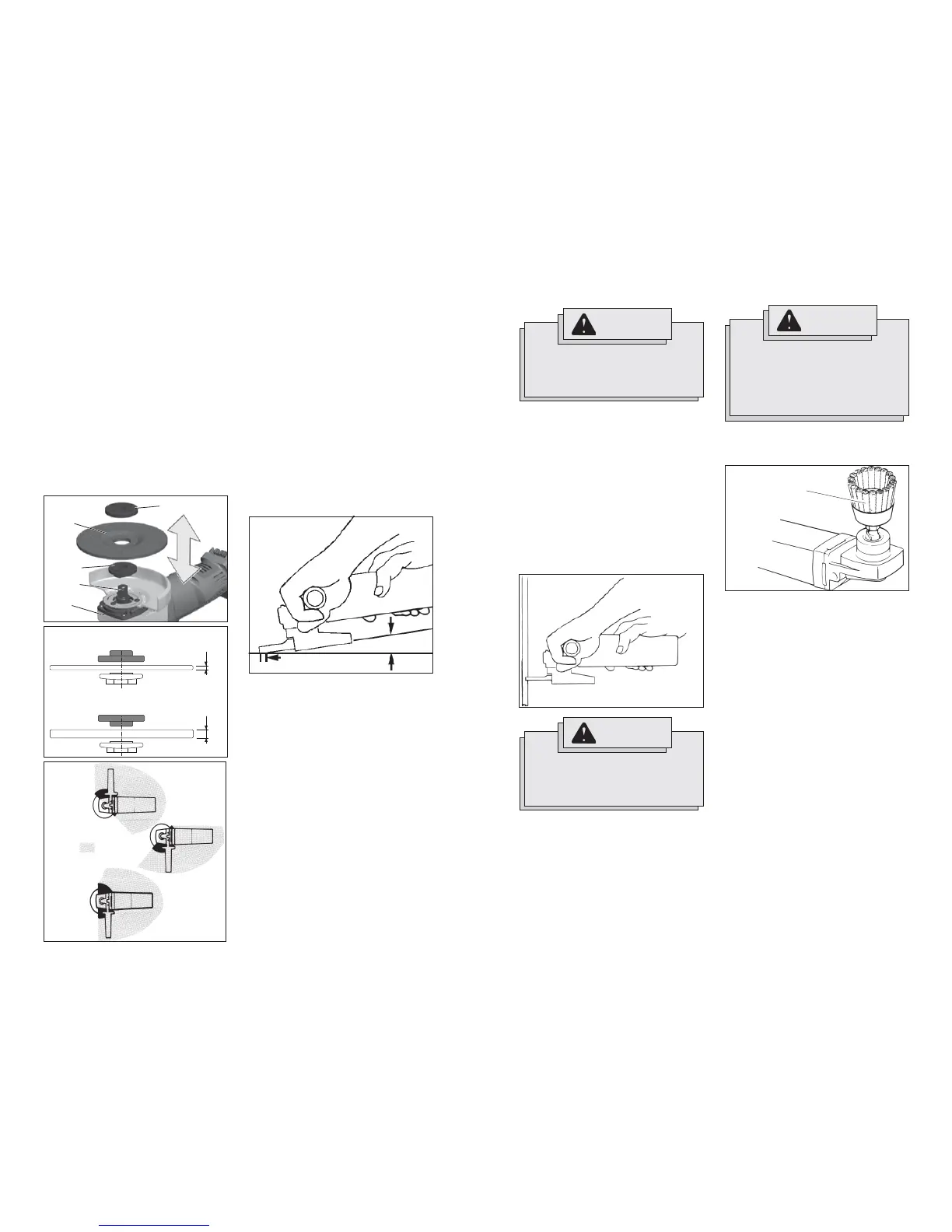
Fig. 3
1/8"
1/4"
Grinding
1. If you have just installed a grinding wheel
or are just beginning a period of work,
test wheel by letting it spin for one min-
ute before applying it to the workpiece.
NOTE: Out-of-balance wheels can mar
workpiece, damage the tool, and cause
stress to wheel that may cause wheel
failure.
2. Use a clamp, vise or other practical
means to hold your work, freeing both
hands to control your tool.
3. When grinding, hold sander/grinder at a
5
o
to 15
o
angle, using constant pressure
for a uniform fi nish. Too great an angle
causes concentrated pressure on small
areas which may gouge or burn work
surface.
Fig. 6
For best result use
only this portion of disc
5° to 15° angle
Installing/Removing Grinding Wheels
1. Remove the battery pack.
2. Properly position the guard (see Fig. 5).
3. Place the fl ange on spindle (see Fig. 4
for proper orientation).
4. Place the selected wheel on the spindle
and align it with the fl ange.
5. Position the fl ange nut over the spindle
according to wheel thickness (see Fig. 4
for proper orientation).
6. Press in the spindle lock button while
turning the fl ange nut clockwise. Tighten
securely using a spanner wrench.
7. To remove wheel, remove the battery
pack and reverse the procedure.
4. To start the tool, grasp the handle and
side handle fi rmly and slide the switch
to ON.
5. Allow grinding wheel to come to full
speed before beginning work.
6. Control pressure and surface contact
between wheel and workpiece. Too
much pressure slows grinding speed.
7. To stop the tool, release the switch.
Make sure the tool comes to a complete
stop before laying the tool down.
8. To lock-on the switch, slide the switch
to ON and then press down on the front
of the switch. To stop the tool, press and
release the switch. Make sure the tool
comes to a complete stop before laying
the tool down.
Installing Wire Cup Brushes
2. To install, thread wire cup brush onto
spindle. Press the spindle lock button
while tightening brush with a 7/8" open
end wrench (not provided with tool).
3. To remove wire cup brush, unplug tool
and reverse procedure.
1. Unplug tool and place it upside down on
a level surface as shown. Remove any
accessories from spindle.
Fig. 8
Wire Cup Brush
WARNING
Everyone in the area must wear pro-
tective clothing and safety goggles
or face shields. Fatigued wires and
residue will fl y off the brush with con-
siderable force, causing potential for
serious injury.
Fig. 7
WARNING
A Type “1” guard must be installed
when using a cut-off wheel to provide
maximum protection for the operator
if the wheel should break.
WARNING
Using the face of a Cut-Off Wheel (as
in grinding) will cause the Wheel to
crack and break, resulting in serious
personal injury.
Type “1” Cut-Off Wheels are suited for
small cut-off and shallow notching opera-
tions only.
1. Firmly grasp body of tool and side
handle before starting and while using
tool. Allow wheel to come to full speed
before starting.
2. When using a cut-off wheel, hold
Sander/Grinder as shown, using only
the edge of the wheel.
3. Control pressure and surface contact
between disc and workpiece. Too much
pressure slows cutting speed.
Using Cut-Off Wheels