digital snap, crackle and pop,severe background noise or total silence—communication
between the devices breaks down completely.If your system consists of a fairly
sophisticated array of digital devices,you will have to synchronize it externally.
Your most consistent but also expensive option is an external clock generator. It dictates
the clock frequency to all devices in the studio.Picture a star-shaped network.The clock
generator is located at its center and transmits its Word Clock signal to all digital devices
located at the points of this star.AN/DI PRO is equipped with a Word Clock input so that it
can accommodate this synchronization option.
In most cases however, you're not compelled to spend your hard-earned money on a clock
generator, at least not for synchronizing the AN/DI PRO. It comes with a truly a unique
feature,the AES/EBU and S/PDIF Sync ports.As you already know,every AES/EBU and
S/PDIF signal contains clock information.This means that all you have to do is check the
other synchronized devices in your digital setup to locate a digital output that happens to
be free.Connect that output to one of the Sync ports of the AND/DI PRO, and the internal
clock of the AN/DI PRO will automatically lock up to the frequency of the other device!
2.Control Features
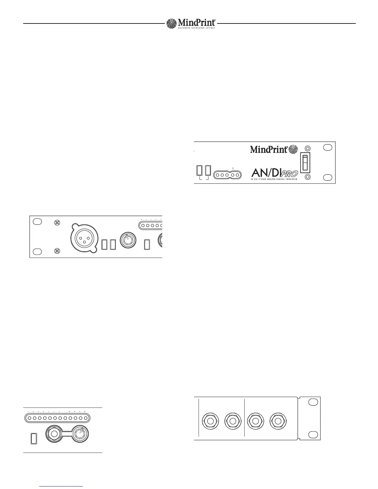
The control features of the AN/DI PRO are arrayed from left to right.This arrangement is in
keeping with the signal flow in the device.
2.1 Microphone Preamplifier
Mic In: XLR input designed to take microphones. The pin assignments of the XLR socket
comply with the international norm IEC 268-12.In accordance with this standard,Pin 1 is
connected to ground,Pin 2 carries the positive signal and Pin 3 the negative signal.
48 V:This button switches phantom power on, which is then fed to the connected
microphone.Dynamic microphones don't require phantom power. Since condenser
microphones do,be sure to press this button with condenser mics.
-20 dB:This button attenuates the level of the microphone input by 20 decibels. In normal
operation,this button should remain out.When you're dealing with very loud microphone
signals,press it in.
Mic Gain: Use this Gain control to adjust the level of AN/DI PRO's microphone input.You
can visually monitor the level on the 12-segment LED meter located above the line input,
provided that the microphone input is activated via the Mic/Line button. If the level
remains too high even when you've turned the knob all the way down,press the -20 dB
button in.
2.2 Line Input
Mic/Line: Use this switch to select either
the microphone input or line input so that
the desired circuit will be routed to the
A/D converter.
Line In: 1/4" jack designed to take line
level signals.You can route both balanced
and unbalanced signals to this input.
Balanced signals are routed via a stereo 1/4" plug,where the tip is the positive signal,
the ring is negative,and the sleeve is connected to ground.When you insert an unbalan-
ced mono plug, the input automatically switches to unbalanced operation.
Line Gain: Use this Gain control to adjust the level of AN/DI PRO's line input.You can
visually monitor the level on the 12-segment LED meter located above the line input,
provided that the line input has been activated (Mic/Line button).
LED Meter:This display indicates the level of the microphone or line input signal,
depending on the status of the Mic/Line button.The yellow LEDs indicate the headroom of
the AN/DI PRO, the red LEDs indicate clipping.
2.3 A/D Converter and Mains Switch
44.1 / 48 / 96 Buttons:These buttons select the sampling frequency.If you require
settings of 44.1 or 48 kHz, press the corresponding button. If both buttons are pressed,
AN/DI PRO operates at 96 kHz.If you don't press any of the buttons, the unit will expect
an external signal to provide synchronization.This external signal has to be fed to the
AN/DI PRO via one of the Sync ports located on the rear panel.
Sampling Freq:The LEDs labeled 44.1, 48 and x2 indicate the currently selected sampling
rate.If you are using an external synchronization source, the LEDs labeled AES and S/PDIF
will indicate that the device is receiving a valid signal.AN/DI PRO syncs at 32 kHz,
44.1 kHz, 48 kHz,88.2 kHz, and 96 kHz. Please refer to page 12.
Mains Switch: Switches the AC power supply on and off.
3.Connections
3.1 Microphone and Line Inputs
The inputs of the AN/DI PRO are located on the front panel.See Section 2 for an
in-depth description.
3.2 Insert Jacks
The Insert inputs are balanced 1/4" jacks (6.3 mm), although you can also connect
unbalanced cables.
In these TRS, stereo-style 1/4" jacks, the positive signal is routed via the tip, the negative
signal via the ring, and the ground is connected to the sleeve.When you insert an
unbalanced mono plug, the Send or Return circuit is automatically switched to
unbalanced operation.
MindPrint-AN/DI PRO


 To Next Page
 Loading...