EasyManua.ls Logo

MINN KOTA MK315 - User Manual

MINN KOTA MK315
9 pages
Print Icon
To Next Page IconTo Next Page
Loading...
OWNER’S MANUAL FOR
MINN KOTA ONBOARD
BATTERY CHARGERS
Models: MK110,MK210,
MK220, MK315, MK330
Service Information:
Please call our service department
at 800-227-6433 if you have any
problems with your battery charger.
A technical support representative
will be happy to assist you.
Compliant with FCC
PART 15,Class B
Question and Answer IconNeed help?

Do you have a question about the MINN KOTA MK315 and is the answer not in the manual?

Summary

Safety Information

Important Safety Instructions

Manual contains vital safety and operating guidance for efficient use; save these instructions.

Risk of Explosive Gases

Working near lead-acid batteries is dangerous due to explosive gases and sulfuric acid.

Personal Safety Precautions

Take personal safety measures near batteries, including protective gear and emergency supplies.

Preparing to Charge

Battery Preparation Steps

Follow steps for battery removal, terminal cleaning, and adding distilled water for safe charging.

Connection and Grounding Procedures

DC Output Terminal Connection

Ensure correct polarity when connecting charger output leads to battery terminals for proper function.

AC Power Cord Grounding and Safety

Ground charger properly; never alter AC cord or use adapters to prevent shock/fire.

Installing the Battery Charger

Choosing the Mounting Location

Mount charger in protected, ventilated area away from corrosive gases, water, and fuel sources.

Mounting and Securing the Charger

Securely mount charger with bolts, nuts, and washers to prevent damage from vibration.

Connecting Batteries Safely

Follow steps to connect charger output leads to battery terminals, ensuring correct polarity and safety.

Operating Instructions

Understanding Indicator Lights

Interpret GREEN, YELLOW, and RED lights for AC power, charging status, full charge, and fault conditions.

Operational Cautions and Warnings

Disconnect power for RED light; avoid charging during storms and use sine wave generators.

Maintenance, Cleaning, and Storage

Service and Cleaning Procedures

Perform only authorized servicing; clean terminals/unit with approved solutions, coil cord, store dry.

FCC Compliance and Specifications

Equipment complies with FCC Class B rules; view technical specifications for models, output, and input details.

Environmental Compliance Statement

WEEE Directive Information

Understand WEEE Directive for responsible disposal of electrical and electronic equipment.

Limited Three Year Warranty

Warranty Service and Limitations

Details warranty terms, exclusions, service, and limitations on implied warranties and damages.

Overview

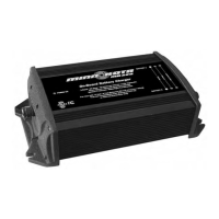
The Minn Kota On-Board Battery Charger is a powerful electrical device designed for charging and maintaining 12-volt 6-cell lead-acid batteries. It is suitable for use with FLOODED/WET CELL, MAINTENANCE FREE, and AGM/STARVED ELECTROLYTE batteries. The charger is not intended for use with dry-cell batteries or for supplying power to low voltage electrical systems other than for charging and maintaining batteries.

Function Description:

The Minn Kota battery charger provides a fully automatic charging process with multiple banks, allowing for independent charging of multiple batteries or combinations of batteries hooked in series or parallel without disconnecting them from any switches or wires/straps. Each output cord is equipped with a temperature sensor that adjusts the charging profile to ensure full charge without overcharging or undercharging, optimizing battery life. The charger is designed with short circuit/reverse polarity protection, ignition protection, and watertight construction for enhanced safety and durability.

Important Technical Specifications:

The manual covers several models with varying specifications:

  • MK110: 12V system, 1 bank, 10 amps per bank, 10 total amps. Dimensions: 10-1/2" x 7-1/2" x 4". Weight: 10 lbs. Input Current: 2.5A (120VAC, 60Hz).
  • MK210: 12/24V system, 2 banks, 5 amps per bank, 10 total amps. Dimensions: 11-1/2" x 7-1/2" x 4". Weight: 11 lbs. Input Current: 2.5A (120VAC, 60Hz).
  • MK220: 12/24V system, 2 banks, 10 amps per bank, 20 total amps. Dimensions: 13-1/2" x 7-1/2" x 4". Weight: 15 lbs. Input Current: 4.4A (120VAC, 60Hz).
  • MK220S: 12/24V system, 2 banks, 10 amps per bank, 20 total amps. Dimensions: 13-1/2" x 7-1/2" x 4". Weight: 15 lbs. Input Current: 4.4A (120VAC, 60Hz). Features an 8.5' input cable.
  • MK315: 12/24/36V system, 3 banks, 5 amps per bank, 15 total amps. Dimensions: 12-1/2" x 7-1/2" x 4". Weight: 14 lbs. Input Current: 2.7A (120VAC, 60Hz).
  • MK330: 12/24/36V system, 3 banks, 10 amps per bank, 30 total amps. Dimensions: 16-1/4" x 7-1/2" x 4". Weight: 20 lbs. Input Current: 5.2A (120VAC, 60Hz).
  • MK330S: 12/24/36V system, 3 banks, 10 amps per bank, 30 total amps. Dimensions: 16-1/4" x 7-1/2" x 4". Weight: 20 lbs. Input Current: 5.2A (120VAC, 60Hz). Features an 8.5' input cable.

All models utilize an 18AWG input cable and 16AWG output cables. The output cords are 6 feet long, with the exception of the 'S' models which have an 8.5' input cable. The maximum extension length for DC battery leads is 15 feet, using a minimum of 12 AWG wire.

Usage Features:

  • Mounting: The charger should be mounted flush on a bulkhead in a protected area away from rain or spray, and never above batteries due to corrosive gasses. A minimum of 6 inches of unobstructed area should be allowed on all sides for proper air circulation and cooling. When mounting to an aluminum boat, isolation (e.g., wood or plastic) should be used to prevent contact between the metallic charger body and the hull, eliminating the risk of electrolysis.
  • Battery Connection: The charger is designed for permanent mounting and connection to batteries. DC output terminals must be connected with correct polarity (RED to POSITIVE, BLACK to NEGATIVE). Connections should only be made after removing the AC plug from the electric outlet. When batteries are connected in series (e.g., for 12/24V or 12/24/36V systems), the series connection wire should remain in place during charging.
  • Indicator Lights:
    • GREEN power light: Indicates AC power is applied.
    • YELLOW light (per bank): Indicates the battery is charging.
    • GREEN light (per bank): Indicates the battery is fully charged and in maintenance mode.
    • RED light (per bank): Indicates no battery connected, reverse polarity, or a short circuit.
    • RED and GREEN lights (simultaneously per bank): Indicates battery voltage below 4 volts (battery should be replaced) or a damaged temperature sensor on the output cord.
  • Safety Precautions:
    • Always ensure the area around the battery is well ventilated during charging.
    • Wear complete eye and clothing protection when working near lead-acid batteries.
    • Never smoke or allow sparks/flames near batteries.
    • Avoid dropping metal tools onto batteries to prevent sparks.
    • Remove personal metal items (rings, bracelets, etc.) when working with batteries.
    • Do not charge a frozen battery.
    • Do not recharge batteries with the watercraft or motor lower unit in the water during electrical storms.
    • Only use generators with a sine wave output; modified square wave output generators can damage the charger.
  • Grounding: The charger is equipped with a grounded AC power cord and plug, which must be plugged into a properly installed and grounded outlet. Adapters should not be used.
  • Extension Cords: Use of an extension cord is not recommended unless absolutely necessary. If used, ensure it is properly wired, in good electrical condition, and of the correct gauge (e.g., 16 AWG for 25 ft, 14 AWG for 50 ft, 12 AWG for 100 ft).

Maintenance Features:

  • Cleaning: Regularly check the battery charger and ring terminals for dirt, oil, and battery corrosion. Clean corrosion with a water and baking soda solution, then wipe clean with a dry cloth.
  • Storage: When not in use, coil the power cord to prevent damage. Store the battery charger in a clean, dry area.
  • Fuse Replacement: Each output cord has inline fuses on the RED and BLACK leads near the ring terminals. If a fuse blows, replace it with the exact type and rating of the original fuse.
  • Troubleshooting: If a RED light is lit, disconnect AC power immediately and determine the cause. If unable to remedy the situation, contact Minn Kota Service Department.
  • Battery Fluid Level: For batteries with removable cell caps, check the battery fluid level every 30 days and add distilled water after the battery has been charged, ensuring not to overfill and replacing all cell caps.

Warranty:

Johnson Outdoors Marine Electronics, Inc. offers a three-year limited warranty on the entire Minn Kota battery charger, covering defects in materials and workmanship from the date of purchase. The warranty does not cover commercial use, normal wear and tear, blemishes not affecting operation, or damage caused by accidents, abuse, alteration, modification, misuse, or improper care. Warranty service in the U.S. requires sending the charger and proof of purchase to the Minn Kota factory service center. For purchases outside the U.S., contact Johnson Outdoors Canada. Retailers are not authorized to repair or replace units under warranty.

MINN KOTA MK315 Specifications

General IconGeneral
ModelMK315
Number of Banks3
Input Voltage120V AC
Automatic Shut-offYes
Output Amperage15 amps
Output per Bank5 amps
Battery Type12V
Output Voltage12V
Compatible Battery TypesAGM, Gel

Related product manuals