Do you have a question about the Mira Sport and is the answer not in the manual?
The Mira Sport must be properly earthed for safety.
Avoid twisting individual live and neutral cable cores to ensure proper connection.
Insulate pipework susceptible to freezing to prevent damage.
Do not operate the Mira Sport if frozen; allow it to thaw first.
Water leaks from the pressure relief valve require maintenance before use.
Do not fit external flow controls; only use Mira recommended fittings.
Only competent tradespeople should access internal components.
Isolate supplies and contact for specific fault conditions like damage or noise.
Always isolate electrical and water supplies before removing the cover.
Mains connections are exposed when the cover is removed.
Ensure electrical connections are tight to prevent overheating.
Read all instructions, retain the guide, and pass it on with ownership.
Electrical installation must comply with IEE Wiring Regulations and local practices.
Contact electricity supplier to ensure supply adequacy for this high power unit.
Plumbing installation must comply with UK Water Regulations and local practices.
Supervise users with difficulty operating controls, like the young or elderly.
Dispose of the Mira Sport safely according to local authority recycling policies.
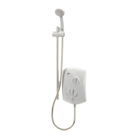
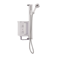
Lists the physical components included with the Mira Sport 10.8 kW.
Lists the documentation provided with the Mira Sport.
Details minimum and maximum inlet pressures for satisfactory operation.
Specifies fuse requirements and terminal block cable size limits.
Lists compliance with BEAB, UK Water Regulations, and CE marking directives.
Covers water pressure, supply type, positioning, and connections.
Details mains-fed and cistern-fed supply requirements for installation.
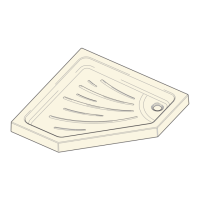
Specifies positioning over a water catchment area at a convenient height.
Mount on a flat surface; avoid tiling up to the case for air circulation.
Avoid installing in locations where the unit might freeze.
Use a non-restrictive isolating valve for maintenance.
Pre-solder pipework before connecting to the inlet connector assembly.
The outlet has a ½" BSP male thread for connecting a shower hose.
Flush supply pipework to remove debris before connecting the Mira Sport.
Consider water treatment for hard water areas to prevent limescale.
Use a hose retaining ring to prevent back-siphonage.
Avoid sharply kinking the shower hose to maintain its lifespan.
Details requirements for electrical supply, fuses, and consumer units.
Ensure domestic electrical supply and consumer unit are adequate for the shower.
Isolate electrical and water supplies before starting installation.
Use the supplied template to aid in positioning and drilling for installation.
Position 200mm from ceiling and maintain 25mm gap from spill-over level.
Remove the three screws to detach the shower unit's cover.
Remove the service tunnel to access internal components.
Determine if the water supply enters from the top, bottom, or back.
Adjust the inlet connector assembly to match the supply direction.
Trim and fit case inserts to accommodate incoming supply pipes.
Flush the cold water supply pipe to remove debris before connection.
Mark fixing holes using the template and ensure electrical cable is accessible.
Drill and plug the top two fixing holes, then drill the bottom hole with the unit in place.
Connect the mains-fed cold water supply pipe to the unit.
Securely connect the cold water supply pipe to the inlet connector.
Route the electrical supply cable into the unit through a designated entry point.
Strip outer cable insulation to allow routing to the terminal block.
Connect conductors, including earth sleeve, firmly into the terminal block.
Re-tighten terminal block screws to ensure secure connections.
Fit an earth bonding clamp to the copper supply pipe if required by regulations.
Reattach the cover and tighten the retaining screws securely.
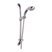
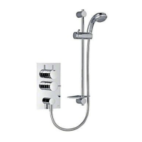
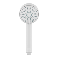
Install the shower handset and hose, following separate instructions.
Ensure electrical and water supplies are isolated before starting.
Review the Operation section before proceeding with commissioning.
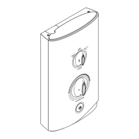
Set the Temperature control knob to the full anticlockwise (cold) position.
Turn on the water supply and check for leaks from the case bottom.
Switch on the electrical supply; the 'Standby' neon indicates connection.
Press 'Low' button; check for water flow from handset within seconds.
Adjust Temperature knob clockwise to check flow regulator operation.
Press 'Medium' button; check for slight rise in water temperature.
Press 'High' button; check for further rise in water temperature.
Adjust the Temperature control knob for desired water temperature.
Press 'Stop' button to halt flow; water purges, then isolate power.
A slight hissing sound during operation is normal due to pressure/temperature.
Explains how electric showers work and basic operation principles.
Explains how the shower heats water by passing it over elements.
Adjust temperature by varying cold water flow across elements; keep spray plate clean.
The shower stabilizes temperature changes caused by water pressure fluctuations.
Seasonal changes or voltage fluctuations may require temperature knob adjustment.
Requires minimum 1.0 bar running pressure; low flow turns off elements.
Thermal switch turns off elements at unsafe temperatures; 'Overheat' neon indicates this.
The shower is not thermostatic and can reach scalding temperatures; supervise users.
Always check the shower temperature before entering the shower.
Expect a slight delay before water temperature changes after selection.
Keep spray plate holes clear by regular cleaning to ensure performance and prevent failure.
Switch on the shower using the pullcord or wall-mounted switch.
Press 'High', 'Medium', or 'Low' buttons to select the desired power level.
Allow 15-20 seconds for warm water to reach the shower handset.
Turn the 'Temperature' knob clockwise to increase, anticlockwise to decrease temperature.
Press the 'Stop' button to turn off the water flow from the handset.
A small amount of water may drain from the fitting after shutdown.
Switch off the main power supply at the pull-cord or wall switch.
Maintenance should only be performed by a competent tradesperson.
No user-serviceable components; only competent tradespeople should remove covers.
Clean fittings with mild detergent and a soft cloth; avoid abrasives.
Detailed steps for removing and installing the flow valve assembly.
Isolate electrical and water supplies before working on the flow valve assembly.
Remove the outlet connector from the heater tank.
Detach the flow valve from related assemblies and the heater tank.
Note the positions of solenoid wires before disconnecting them.
Complete the removal of the flow valve.
Refit components in reverse order, ensuring correct wire placement.
Detailed steps for removing and installing the heater tank.
Isolate electrical and water supplies before removing the heater tank.
Remove cover and service tunnel to access the heater tank.
Detach the hose and loosen the inlet connector assembly.
Unscrew and remove the terminal block.
Remove the splash guard between the heater tank and flow valve.
Remove the screws holding the inlet clamp bracket.
Remove screws holding the flow valve, PCB, and heater tank.
Carefully pull out the flow valve, PCB, and heater tank assemblies.
Note the positions of wiring connections on top of the heater tank.
Disconnect black and red wires from the PCB.
Remove bonding strip and wires from the thermal switch.
Disconnect green and blue wires from the top of the heater tank.
Do not press the thermal switch's printed disc, as it will make it unserviceable.
Remove the fixing screw and detach the thermal switch.
Separate the heater tank from the flow valve and PCB assemblies.
Detach the outlet connector from the heater tank.
Refit components in reverse order, ensuring correct wire placement.
Detailed steps for removing and installing the thermal switch.
Isolate electrical and water supplies before removing the thermal switch.
Remove cover and service tunnel to access thermal switch.
Detach the hose and loosen the inlet connector assembly.
Unscrew and remove the terminal block for access.
Remove screws securing the inlet clamp bracket.
Remove screws holding flow valve, PCB, and heater tank.
Carefully pull out the flow valve, PCB, and heater tank assemblies.
Remove bonding strip and wires from the thermal switch.
Disconnect green and blue wires from the heater tank top.
Remove the fixing screw and detach the thermal switch.
Do not press the printed disc on a replacement thermal switch.
Refit components in reverse order, ensuring correct wire placement.
Steps to remove, clean, and refit the inlet filter.
Detailed steps for removing and installing the Printed Circuit Board.
Isolate electrical and water supplies before working on the PCB.
Remove cover and service tunnel for PCB access.
Detach hose and loosen inlet connector assembly.
Unscrew and remove the terminal block for access.
Remove screws securing the inlet clamp bracket.
Remove screws holding flow valve, PCB, and heater tank.
Carefully pull out the flow valve, PCB, and heater tank assemblies.
Note the positions of wiring connections on the PCB.
Disconnect red/brown wires and busbar from the top of the PCB.
Note wiring positions on the top of the heater tank.
Disconnect brown, blue, and green wires from the heater tank top.
Note wiring positions on the bottom of the solenoid valve.
Disconnect black and red wires from the bottom of the solenoid valve.
Detach the PCB assembly and all associated wiring.
Refit components in reverse order, ensuring correct wire placement.
No user-serviceable parts; only competent tradespeople should access.
Provides user-level troubleshooting steps without cover removal.
Contact your installer if remedies do not resolve the problem.
Addresses issues of no water or very low flow rate.
Addresses failure to produce hot water in any setting.
Addresses intermittent temperature fluctuations.
Continues troubleshooting steps for common issues.
Addresses inability to achieve a cool enough shower, especially in summer.
Addresses when the temperature knob has minimal impact on water temperature.
Lists part numbers and names for common Mira Sport components.
Prevents backflow/backsiphonage; increases required supply pressure by 0.1 bar.
Outlines the one-year guarantee against defects and conditions for validity.
Information on how to get expert assistance and support for product issues.
Details availability of spare parts for up to ten years from manufacture.
Advice on checking simple maintenance issues first before contacting support.
Provides contact numbers and addresses for customer service in various regions.
| Type | Electric Shower |
|---|---|
| Warranty | 2 years |
| Power Ratings | 10.8 kW |
| Installation | Wall Mounted |
| Controls | Push-button |
| Safety Features | Over temperature protection, phased shutdown |
| Water Pressure | Minimum 0.7 bar |