5
Kaleido-X (4RU)
Hardware Description & Installation Manual
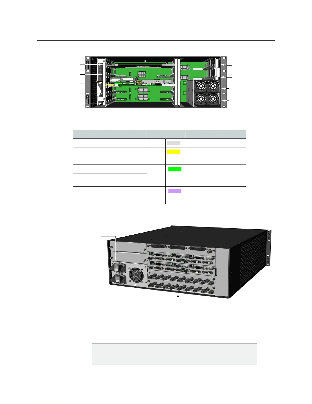
The illustration above shows the location of the available slots in the frame. The function of
each slot is given in the following table:
The rear of the frame holds the rear connector panels for the cards, the AC power
connectors with integral ON/OFF switches, and a fan for power-supply cooling.
Monitoring the Temperature of the Kaleido-X
For optimal performance, it is strongly recommended that you operate the Kaleido-X in an
environment with an ambient temperature lower than 20
ºC (68 ºF).
Slot Function Color code Card type
1 Main Grey KXA-GPI-GEN
2 Output A Yellow KXO-Dual3, KXO-Dual
3 Output B
4 Input A Green KXI-16HSV3, KXI-16HSV
KXI-16HS3, KXI-16HS
KXI-16SV
5 Input B
6 Option A Mauve Future Use
7 Option B
IMPORTANT
When measuring the ambient room temperature, take your readings
from directly in front of the Kaleido-X frame.
Slot #
5
Slot #
6
4
3
7
2
1
PSU A
PSU B
AC power sockets with
ON/OFF switches
Power supply cooling fan
Rear connector panels

 Loading...

