18 19
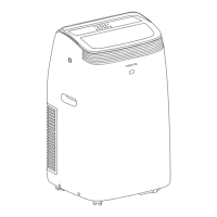
¢ INSTALLATION OF INDOOR UNIT
• Let pipe go through the wall hole and attach
the indoor unit to the mounting plate.
(Locate the rib of the indoor unit in the hole
of the mounting plate.)
¢ THE CONNECTION OF PIPE
• The number of bends in the pipe of the
indoor unit should not exceed 10. The
number of bends in the pipe of the indoor
unit and outdoor unit should not exceed 15.
• The radius of bends should be more than 10cm.
A layer of air proof oil should be coated on the
joint before the pipe has been connected. Align
the axis of each pipe and tighten screw nut with
a spanner (see the right diagram).
PIPE DIAMETER OF PIPE TORQUE (N • m)
Liquid pipe 6.35mm (1/4") 13.7---17.6
Gas pipe 9.52mm (3/8") 34.3---41.2
Gas pipe 12.7mm (1/2") 49.0---56.4
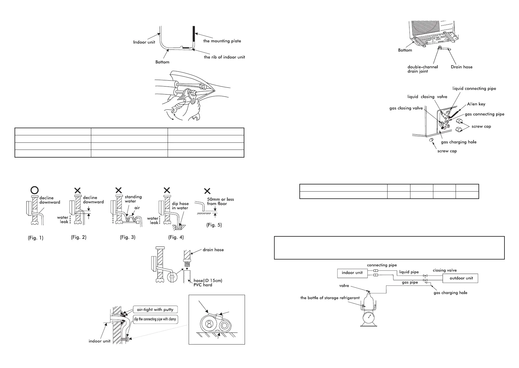
¢ ARRANGEMENT OF DRAIN HOSE
• To eject the condensated water easily, the drain hose should be positioned downward.
The arrangement in diagrams 2-5 are wrong.
• If the drain hose connected with the indoor
unit is short, it may be extended by the hose
in the accessory box.
• When the drain hose must be run through
the house, it should be wrapped by the
special heat insulated materials.
¢ SEALING OF WALL HOLE AND
FASTENING OF PIPE
• Use putty to seal the wall hole.
• Use clamp (pipe fastener) to secure
the pipe at specied position.
dispose of unwanted part
screw
clamp
¢ INSTALL THE DRAIN JOINT
(heat pump type only)
• Install the double-channel drain joint in the
hole on the bottom of the outdoor unit's
bottom, then connect drain hose and joint.
¢ CONNECT CONNECTING PIPE
• Wipe the air sealing oil on the closing valve
and the trump extended pipe; Screw down the
nut of connecting pipe with the wrench.
(the torque is as the indoor unit)
¢ DISCHARGING THE AIR WITHIN THE UNITS:
• Unscrew cap for closing valve gas
charging hole.
• Open the closing valve with Allen key (turn
90˚ clockwise), then push in the gas charging
hole for about 10 seconds, (Until a gas like
fog appears, this indicates the air within unit
is fully discharged.)
• Screw down the screw cap of the gas
charging hole.
• Test for leaks with leak detector or soapy water.
¢ ADD REFRIGERANT
• If the connecting pipe is longer than 7 meters, add refrigerant as needed.
(Heat pump type) A=(Lm-7m)x50g/m. (A: add refrigerant amount, L: the length of connecting pipe)
the length of connecting pipe (m) 7 8 9 10
(Heat pump type) add amount (g) 0 50 100 150
• Connect the refrigerant gas bottle with the gas charging hole;
(do not screw down the nut of the gas closing valve's end.)
• Open the bottle's valve of storage refrigerant, discharge the air of units with refrigerant;
• When gas like fog appears, indicating the air of unit is discharged, screw down the nut;
• Add refrigerant with the spring balance.
NOTE: • Do not overturn the bottle of storage refrigerant, when adding refrigerant to the unit;
• Heat up the bottle of storage refrigerant with warm water (about 40˚C), do not
use an exposed ame or hot steam.
¢ TEST
• Start leak test (with leak detector or soapy water) and inspect connecting cables before testing
operation. Test procedure: (Control unit by emergency operation switch or remote controller)
For detailed operation see "OPERATION OF AIR CONDITIONER."
 Loading...