Do you have a question about the Mitsubishi Electric AE-SW Series and is the answer not in the manual?
| Brand | Mitsubishi Electric |
|---|---|
| Model | AE-SW Series |
| Category | Circuit breakers |
| Language | English |
Identifies the specific AE-SW model series covered in this manual.
Provides critical initial warnings and instructions before operating the AE Series breakers.
Lists the specific AE Series air circuit breaker models included in this manual.
Explains the meaning of danger, caution, and prohibition symbols used throughout the manual.
Details essential safety measures to prevent severe injury or death from hazardous situations.
Outlines necessary precautions to avoid potential hazards and product damage.
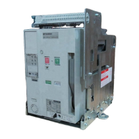
Illustrates and labels the external parts of the fixed type air circuit breaker.
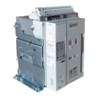
Illustrates and labels the external parts of the drawout type air circuit breaker.
Lists and numbers the various internal components comprising the air circuit breaker.
Provides detailed dimensions and weight specifications for different breaker models.
Guides users through the process of unpacking the breaker and verifying its condition.
Specifies required environmental conditions and precautions for safe storage of the breaker.
Details methods and precautions to ensure the breaker is handled safely during transportation.
Provides a step-by-step guide for installing the drawout type breaker and its cradle.
Details the mounting process for the fixed type breaker, including safety considerations.
Describes how to install the drawout handle on either the left or right side of the cradle.
Explains the procedure for inserting the inter-phase barrier into the breaker.
Instructions and diagrams for connecting main circuit conductors to the breaker terminals.
Guidelines for selecting conductors based on current capacity and electromagnetic forces.
Instructions for connecting wires to the control circuit terminal block, including torque specifications.
Details the initial steps for inserting the drawout type breaker, including lock lever and rail operations.
Final steps for securing the breaker, involving lock plate engagement and drawout handle rotation.
Details the initial steps to begin drawing out the breaker, including handle and lock plate manipulation.
Completing the drawout to the DISCONNECT position and detaching the breaker from the cradle.
Instructions for manually charging the closing spring using the charging handle.
Details the optional motor charging system, including rating and circuit diagram.
Lists the requirements for performing a closing (ON) operation on the breaker.
Explains how to manually close (ON) and open (OFF) the breaker.
Describes how to electrically close the breaker using the closing coil (CC).
Explains electrical opening using Shunt Trip (SHT) or Undervoltage Trip (UVT) devices.
Details the steps required to release the door interlock mechanism.
Explains how to lock and release the breaker's OFF state using cylinder or Castell locks.
Instructions for resetting the OCR alarm after a trip event.
Guides on using the shutter lock to secure live parts when the breaker is withdrawn.
Instructions for applying 'BUSBARS' and 'CABLES' nameplates to the safety shutter.
Explains the purpose of ETR components like LEDs, buttons, and their indicators.
Illustrates the ETR dial settings and buttons, using a WS1G1 model as an example.
Describes the behavior of the load current LED and the logic behind pre-alarm activation.
Details the different control power supply types and their contact capacities.
Shows the ETR dial layout and explains the setting items for the WS type.
Details characteristic setting ranges, accuracy, and default values for WS type relays.
Illustrates the ETR dial configuration specific to the WM type breaker.
Lists setting ranges, accuracy, and factory default values for WM type relays.
Displays the ETR dial layout and explains the setting items for the WB type breaker.
Details characteristic setting ranges, accuracy, and default values for WB type relays.
Explains the WF type ETR dial settings and how LTD curves are selected.
Lists characteristic setting ranges, accuracy, and default values for WF type relays.
Presents graphs for LTD curve settings (a=0.02, 1, 3, 4) and their operational characteristics.
Provides formulas for calculating LTD and PAL operating times based on selected settings.
Details the settings and characteristics for the G1 module providing ground fault protection.
Explains the E1 module for electric leakage protection, including ZCT requirements.
Describes the AP module for configuring two-stage pre-alarm functions.
Outlines the N5 module's function for neutral pole LTD and pre-alarm characteristics.
Step-by-step guide on how to adjust ETR settings using a screwdriver.
Instructions on using a field testing device to check trip characteristics after making settings.
Demonstrates calculation methods for setting ETR parameters using an AE1600-SW WS1G1 relay.
A table summarizing current values and operating times based on the example settings.
A detailed diagram illustrating the electrical connections for a fully equipped model.
Explains the function and connection for each terminal on the breaker.
Provides specific notes on wiring UVT controllers, coils, and auxiliary switches.
Highlights polarity for DC wiring and safety notes for terminals and alarms.
Specifies required clearances around the arc-extinguishing chamber for safe operation.
Details the standards and test points for insulation resistance and withstand voltage tests.
Defines the conditions for standard and special operating environments for the breaker.
Outlines the warranty terms, coverage, and duration for the air circuit breaker.
Provides guidelines for periodic inspection and maintenance based on operating environment and cycles.
Steps to prepare for inspection, including safety precautions and power shut-off.
Lists initial inspection items, criteria, and standards for resistance/voltage tests.
Specific items for periodic inspection of the breaker's exterior, main circuit, and arc-extinguishing chamber.
Inspection procedures for the electronic trip relay, including appearance and operation characteristics.
Inspection criteria for accessories like coils, switches, shutters, and interlocks.
Guidelines for inspecting the breaker after it interrupts overload or short-circuit current.
Addresses causes and treatments for failure to close, open, or charge the breaker.
Covers issues related to charging failures, abnormal temperature rise, and circuit breaks.
Diagnoses and resolves issues with ETR tripping, display functions, and LEDs.
Troubleshoots problems with drawout/insert operations, safety shutters, terminal blocks, and UVT controllers.
Provides information about Mitsubishi's service network and applicable product types.
Provides contact information, addresses, and branch details for Mitsubishi Electric Corporation.