Do you have a question about the Mitsubishi Electric City Multi PEFY-P200VMH-E and is the answer not in the manual?
| Series | City Multi |
|---|---|
| Refrigerant | R410A |
| Cooling Capacity | 20.0 kW |
| Heating Capacity | 22 kW |
| Power Supply | 380-415V, 50Hz |
| Dimensions (HxWxD) | 300 x 1, 000 x 400 mm |
| Net Weight | 12 kg |
Crucial steps before unit installation and electrical connections.
Explanation of symbols used in text and illustrations for safety warnings.
Key safety advice for installation, operation, maintenance, and disposal.
Guidelines for using, storing, and cleaning refrigerant piping.
Precautions for refrigerant types, oil, and system filling procedures.
Prohibited tools for R410A/R407C systems and reasons for caution.
List of PEFY series models and their corresponding cooling/heating capacities in kW.
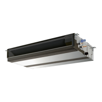
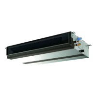
Identifies and illustrates the main indoor unit parts.
Details the PAR-20MAA remote, its display, and operation buttons.
Technical specifications for models PEFY-P40 to P71VMH-E.
Technical specifications for models PEFY-P80 to P140VMH-E.
Technical specifications for models PEFY-P200 to P250VMH-E.
Details on electrical components like transformers, thermistors, and motors.
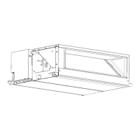
Visual and tabular data for unit dimensions and installation clearances.
Visual and tabular data for unit dimensions and installation clearances.
Schematic showing electrical connections for specific models.
Key to understanding the symbols used in the wiring diagrams.
Schematic showing electrical connections for larger capacity models.
Diagram illustrating the refrigerant circuit and key components.
Table detailing gas and liquid pipe diameters for various models.
Step-by-step guide for testing key components like thermistors and motors.
Instructions for setting the indoor unit address using rotary switches.
Default dip-switch settings for various models and their functions.
Specific instructions for performing a test run with the drain water lift-up kit.
Explanation of LED indicators on the service board for operational status.
Step-by-step guide to remove control box and terminal bed covers.
Procedures for disassembling control box cover and fan motor for larger models.
Detailed steps for removing the fan motor and its components.
Specific procedures for removing fan motors from larger capacity models.
Procedures for disassembling the fan motor on 200-250 series units.
Instructions for removing LEV motors and thermistor sensors from the piping.
Steps to remove the heat exchanger, bottom plate, and drainpan.
Procedures for removing the heat exchanger from larger unit models.
Diagram illustrating the internal component layout of the control box for 40-140 models.
Diagram showing the internal component layout of the control box for 200-250 models.
Visual guide showing the location of liquid and gas sensors for different models.