Do you have a question about the Mitsubishi Electric CITY MULTI PFFY-P24NEMU-E and is the answer not in the manual?
| Series | CITY MULTI |
|---|---|
| Refrigerant | R410A |
| Capacity (Cooling, kW) | 2.4 |
| Capacity (Heating, kW) | 2.8 |
| Power Supply | 220-240V, 50Hz |
| Power Source | Single-phase |
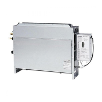
| Indoor Unit Type | 4-way cassette |
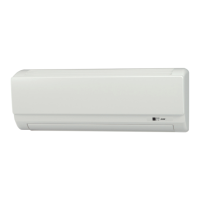
Identifies and explains parts of the indoor unit.
Details the remote controller's buttons and functions.
Lists cooling/heating capacities and physical dimensions for various models.
Details the electrical parts, including transformers, fuses, and motors.
Provides diagrams and measurements for NEMU-E series units.
Provides diagrams and measurements for NRMU-E series units.
Illustrates the wiring connections inside the unit's control box.
Explains the meaning of symbols used in the wiring diagrams.
Specifies gas and liquid pipe sizes for R410A and R22 refrigerants.
Methods for checking thermistors, transformers, and expansion valves.
Thermistor resistance graphs and linear expansion valve operation details.
Addresses issues like valve locking and incorrect wiring connections.
Steps to remove control box and various thermistors.
Procedures for removing the drainpan, fan motor, and heat exchanger.
Steps for disassembling the casing and air diffuser of concealed units.