Do you have a question about the Mitsubishi Electric CITY MULTI PFFY-P20VCM-E and is the answer not in the manual?
| Series | CITY MULTI |
|---|---|
| Cooling Capacity | 2.2 kW |
| Heating Capacity | 2.5 kW |
| Power Supply | 220-240V, 50Hz |
| Refrigerant | R410A |
Explains warning and caution symbols for safety.
Critical safety guidelines for installation and electrical work to prevent hazards.
Specific safety measures for handling R410A refrigerant to ensure proper operation and safety.
Lists cooling and heating capacities for different PFFY-P..VCM-E indoor unit models.
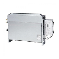
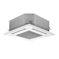
Illustrates the main parts and airflow path of the indoor unit.
Describes the purpose and operation of each button on the remote controller.
Explains the different display modes and icons available on the remote controller.
Details performance metrics like capacity, power consumption, and airflow for various models.
Lists electrical components, their symbols, and specifications, including thermistor resistance values.
Provides detailed drawings and measurements for wall installation of the unit.
Offers detailed drawings and measurements for floor installation of the unit.
Presents the electrical wiring schematic and explains component connections.
Illustrates the refrigerant flow, pipes, and key components like the LEV and thermistors.
Guides on checking thermistors, fan motors, and expansion valves using test methods.
Details LEV operation, common faults like locking or leakage, and remedies.
Step-by-step troubleshooting for indoor unit fan motor failure, including voltage checks.
Covers dip-switch configuration, address setting, and voltage test points on the control board.
Instructions for setting dip-switches for functions and selecting external static pressure levels.
Steps to remove the control box cover and access internal components for maintenance.
Procedure for removing and replacing the intake air thermistor.
Instructions for draining and removing the unit's drain pan.
Steps to remove the LEV and the liquid/gas pipe thermistors.
Guidance on removing the fan motor assembly and the heat exchanger.
Illustrates the locations of gas and liquid sensors for different models.