77
DISASSEMBLY PROCEDURE
PHOTOS/ FIGURES
Photo 6-1
Flow sensor
Photo 6-2
Photo 6-3
O-ring
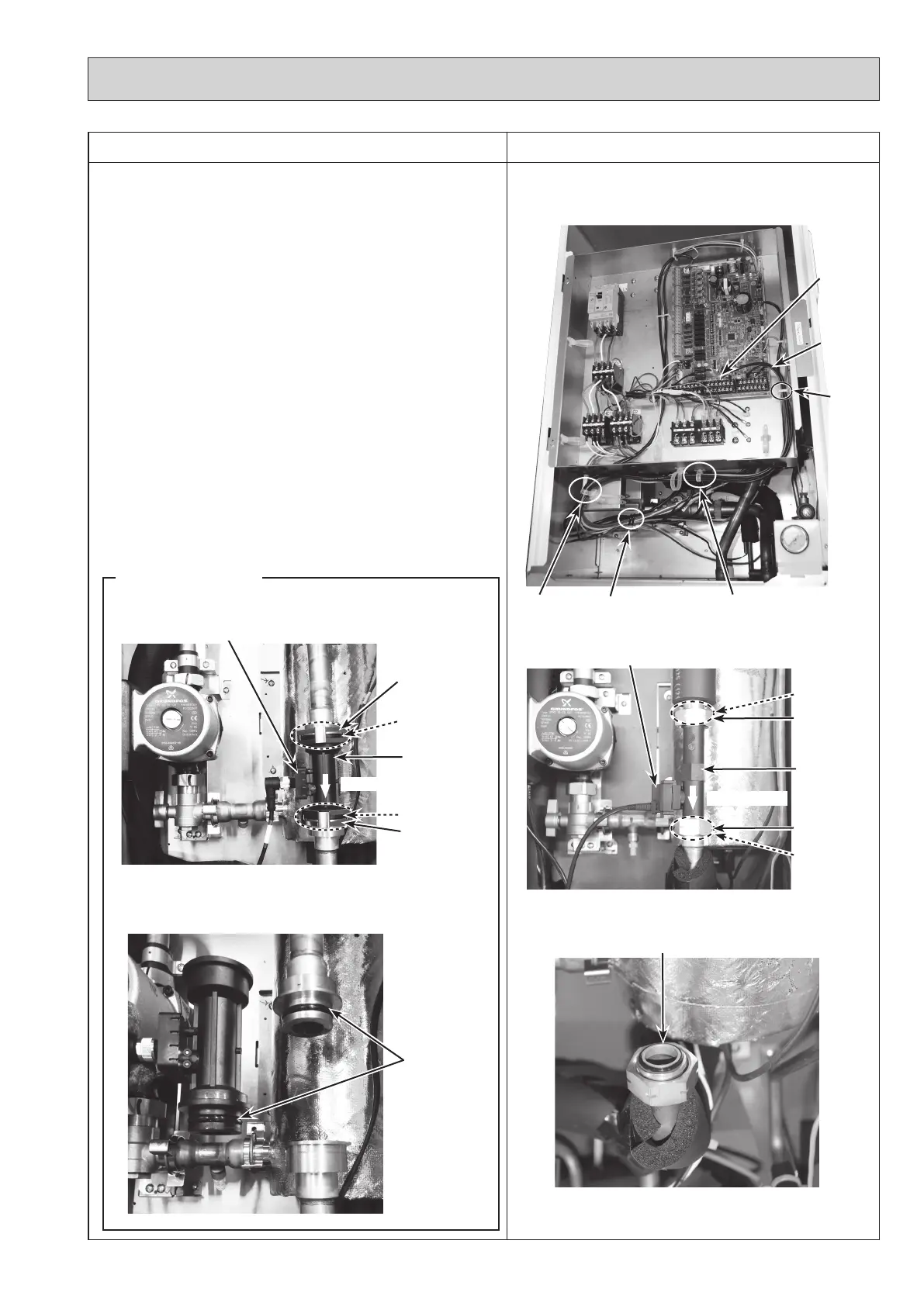
6. How to remove the flow sensor
(1) Remove the front panel. (Refer to Procedure 1.)
(2) Disconnect the CN1A connector on the controller board.
(Photo 6-1)
(3) Release the flow sensor lead wire from the cable clamp,
the 2 cable straps, the coated clamp and feed the lead
wire out the control box without putting strain on the
CN1A connector. (Photo 6-1)
(4)
Swing the control box to the front. (Refer to Procedure 4.)
(5) Remove the flow sensor by removing the nut. (Photo
6-2)
<For R2/R3 models>
(5) Remove the flow sensor by detaching the same diameter
quick connection. (Photos 6-4 and 6-5)
•
When reinstalling the flow sensor, use new O-rings.
(Photo 6-3 and 6-5)
•
Set the flow sensor in the orientation of the arrow
printed on the flow sensor and in the way that the
sensor part faces to the left. (Photo 6-2 and 6-4)
• Refer to page 90 for how to attach and detach the
quick connection.
Nut (G1")
Cable
clamp
Cable strapCable strap Coated clamp
Lead wire
O-ring
Nut (G1")
O-ring
Sensor part
CN1A
connector
Flow sensor
Photo 6-4
Photo 6-5
O-rings
O-ring
Sensor part
R2/R3 models
Flow direction
Flow direction
O-ring
Same diameter
quick connection
Same diameter
quick connection
OCH571D
 Loading...