Pa
18
22
25
23
24
*1
26
7
6
5
8
9
10
11
12
13
15
16
20
21
27
3
19
26
28
28
4
25
26
26
29
Pa
18
19
22
25
23
24
5
3
17
9
10
11
12
13
15
16
20
27
4
6
7
8
*1
25
26
26
21
29
32
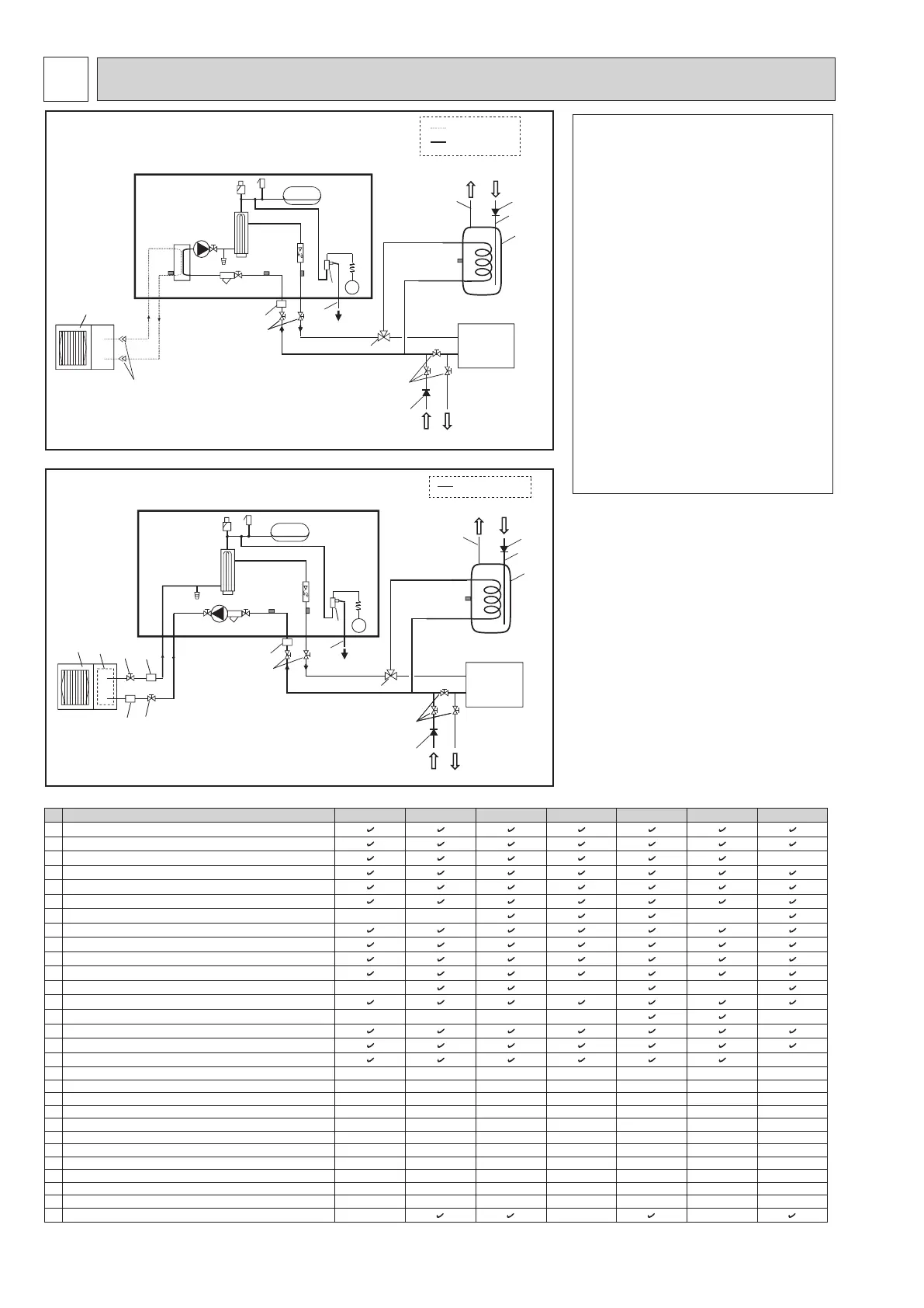
WATER SYSTEM DIAGRAM
8
<Figure 8-1> Water system diagram for Split model
<Figure 8-2> Water system diagram for Packaged model
Notes:
• Be sure to follow your local regulations to per-
form system conguration of the DHW connec-
tions.
• DHW connections are not included in the hy-
drobox package. All required parts are to be
sourced locally.
• To enable draining of the hydrobox an isolating
valve should be positioned on both the inlet and
outlet pipework.
• Be sure to install a strainer on the inlet pipe
work to the hydrobox.
• Suitable drain pipe work should be attached to
pressure relief valves, in accordance with local
regulations, with the exception of 5bar PRV
located next to the expansion vessel.
• The outlet for the 5bar PRV should be open
ended and facing the rear panel. Nothing
should be placed below the Hydrobox.
• A backow prevention device must be installed
on water supply pipework (IEC 61770).
• When using components made from different
metals or connecting pipes made of different
metals insulate the joints to prevent a corrosive
reaction taking place which will damage the
pipework.
<E*S*> (Split model system)
<EHPX> (Packaged model system)
Local
system
Refrigerant pipe
Water supply
Water supply
DHW
DHW
Drain
Drain
Drain
Drain
Cold water
Cold water
Water pipe
Water pipe
Hydrobox
Hydrobox
Flare connections
Local
system
No.
Part name EHS*-MEC EHSD-MC EHS*-*M*C EHSC-*M*EC ERS*-VM2C ERSC-MEC EHPX-*M*C
1
Control and electrical box
2 Main remote controller
3 Plate heat exchanger (Refrigerant - Water)
-
4 Water circulation pump 1
5 Pump valve
6 Drain cock (Primary circuit)
7 Booster heater 1, 2
- - -
8 Flow sensor
9 Manometer
10 Pressure relief valve (3 bar)
11 Automatic air vent
12 Expansion vessel
- - -
13 Strainer valve
14 Drain pan
- - - - -
15 THW1
16 THW2
17 TH2
-
18 THW5 (Optional part PAC-TH011TK-E or PAC-TH011TKL-E)
- - - - - - -
19 Outdoor unit
- - - - - - -
20 Drain pipe (Local supply)
- - - - - - -
21 3-way valve (Local supply)
- - - - - - -
22 DHW indirect unvented tank (Local supply)
- - - - - - -
23 Cold water inlet pipe (Local supply)
- - - - - - -
24 DHW outlet pipe (Local supply)
- - - - - - -
25 Back ow prevention device (Local supply)
- - - - - - -
26 Isolating valve (Local supply)
- - - - - - -
27 Magnetic lter (Local supply) (Recommended)
- - - - - - -
28 Strainer (Local supply)
- - - - - - -
29 Pressure relief valve (5 bar)
-
*1
*1
-
*1
-
*1
<Table 8-1>
*1 Only E***-*M*CR3.UK model
*
1
Refer to the following section [Local system].
OCH571D