Do you have a question about the Mitsubishi Electric EHST20C-VM6HB and is the answer not in the manual?
| Category | Heat Pump |
|---|---|
| Model | EHST20C-VM6HB |
| Heating Capacity | 5.0 kW |
| Power Input (Heating) | 1.25 kW |
| Energy Efficiency Ratio (Heating) | 4.0 |
| Operating Temperature Range (Heating) | -15°C to 24°C |
| Dimensions (Outdoor Unit) | 800 x 285 x 550 mm |
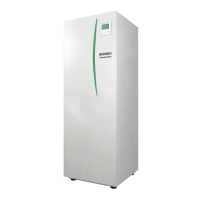
Details the service documentation for the outdoor unit of the system.
Crucial safety instructions to prevent injury, death, and equipment damage.
Highlights critical warnings and cautions for safe operation and handling.
Specific warnings for handling R410A refrigerant during installation and use.
Cautions regarding pipe connection, cleaning, and tool usage for R410A refrigerant.
Guidelines for safe service, refrigerant charging, and necessary service tools.
Detailed specifications including dimensions, weight, performance, and electrical data for various models.
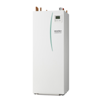
Identifies and illustrates components of EHST20C split model systems.
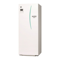
Illustrates and names parts for EHST20C-M-EB without expansion vessel.
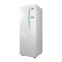
Part identification diagrams for solar split and UK packaged models.
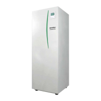
Illustrates and names components of EHPT20X packaged models.
Provides technical drawings with dimensions and connection details for unit layout.
Illustrates service access points and required clearances for maintenance.
Detailed wiring diagrams for various EHST20C models including signal inputs and outputs.
Detailed wiring diagrams for various EHPT20X models, showing electrical connections and components.
Explains dip switch locations and lists settings for various functions and models.
Details field wiring for a 1-phase system where the cylinder unit is powered by the outdoor unit.
Illustrates field wiring for a 3-phase system powering the cylinder unit from the outdoor unit.
Wiring diagram for a 1-phase system with separate power supplies for cylinder and outdoor units.
Wiring diagram for a 3-phase system with separate power supplies for cylinder and outdoor units.
Water system diagrams for EHST20C split and solar split models, showing component connections.
Water system diagram for the EHPT20X-VM2HB UK packaged model.
Water system diagram for EHPT20X packaged models, illustrating water circuit components.
Diagrams for single-zone temperature control with and without a boiler.
Diagrams for dual-zone temperature control with and without a boiler.
Instructions for filling the cylinder unit with primary and potable/DHW water circuits.
Procedures for draining the cylinder unit, including safety warnings for hot water.
Introduces the main controller, its parts, and key icons displayed on the screen.
Menu options for DHW, Legionella, Heating modes, and schedule timers.
Menu paths for heat source, operation settings, and intelligent settings.
Guide to accessing the service menu, password protection, and basic navigation.
How to manually control pump, 3-way valve, and mixing valve for up to 2 hours.
Configuring auto-recovery after power failure and adjusting thermistor readings.
Setting parameters for auxiliary components like pump economy, electric heaters, and mixing valves.
Adjusting electric heater operation times and mixing valve control parameters.
Setting the speed for the water circulation pump.
Configuring heat source priority and freeze protection for the unit.
Enabling simultaneous heat pump and heater operation or cold weather mode.
Adjusting settings for extreme cold weather and room temperature control for heating.
Configuring floor dry up function and external inputs like demand control and outdoor thermostat.
Viewing running information, thermistor readings, and summary of configured settings.
Accessing and interpreting error history for troubleshooting and fault diagnosis.
Setting or resetting the service menu password for security.
Restoring factory default settings for the main controller or FTC4.
Procedures for backing up and restoring main controller settings using an SD card.
Instructions for enabling and disabling emergency heating mode using dip switches.
Instructions for enabling and disabling emergency boiler mode using dip switches.
Guides on diagnosing and resolving issues based on error codes and unit conditions.
Procedures for performing a test run and diagnosing malfunctions via the main controller.
Diagnosing and resolving issues related to circulation water temperature overheat protection.
Troubleshooting steps for tank water temperature overheat protection.
Diagnosing and resolving errors caused by thermistor failures.
Troubleshooting steps for circulation water freeze protection errors.
Diagnosing and resolving issues related to heating operation errors.
Troubleshooting flow rate detection errors in primary and Zone1/Zone2 circuits.
Resolving errors related to boiler operation, freeze protection, and dip switch settings.
Troubleshooting errors associated with thermistors and plate heat exchanger freeze protection.
Diagnosing and resolving communication errors between main controller and indoor/outdoor units.
Troubleshooting reception and transmission errors between indoor and outdoor units.
Resolving communication issues between wireless receiver and remote controller.
Troubleshooting blank display, 'Please Wait', or disappearing main screen.
Diagnosing issues related to FTC4 LED indicators, power supply, and SD card.
Addressing problems like no water at tap, cold water, tripped breakers, or 3-way valve faults.
Resolving issues with slow water heating, dropped DHW tank temperature, and water leakage.
Troubleshooting heating system performance and other faults like incorrectly sized emitters or battery problems.
Diagnosing issues in 2-zone control and heat recovery operation, including 3-way valve faults.
Troubleshooting discharge from primary and sanitary circuit pressure relief valves.
Addressing issues with pressure relief valves, water circulation pump noise, and milky water.
Resolving problems related to operational modes, standby periods, and power recovery behavior.
How to check water circulation pump performance characteristics and flow rates.
Checking the resistance and reset function of the immersion heater.
Checking booster heater resistance, circuit breakers, relays, and flow switch function.
Procedures for checking 3-way valve operation and thermistor resistance characteristics.
Diagram showing test points on the FTC4 controller board for troubleshooting.
Step-by-step guide for removing the front panel and main controller unit.
Instructions for removing control box covers, circuit breakers, contactors, and terminal blocks.
Steps for disconnecting wires and removing the controller board.
Procedures for removing and swinging the control box for access.
Steps for removing the water pump and its associated valves.
Instructions for removing the 3-way valve and its motor assembly.
Steps for removing and reinstalling the flow switch, including correct orientation.
Detailed instructions for removing the booster heater, including disconnecting wires and fasteners.
Steps for removing the thermostat and immersion heater, including sealing precautions.
Instructions for removing the plate heat exchanger, including refrigerant piping and hose disconnection.
Steps to displace and remove the plate heat exchanger and its water pipe.
Instructions for closing valves and removing the strainer and its cover.
Steps for removing the manometer assembly and pressure relief valve.
Instructions for removing the automatic air vent.
Steps for removing the expansion vessel, including flare nut and gasket handling.
Procedure for removing the temperature and pressure relief valve on specific models.
Instructions for removing the manual air vent.
Steps for removing drain cocks from the primary and sanitary circuits.
Instructions for removing flexible hoses from the plate heat exchanger and DHW tank side.
Procedures for removing thermistors, including disconnecting connectors and holders.
Steps for removing the side panels of the unit.
Instructions for removing the back panel, including handle removal.
Guidelines for using loctite remover, applying new loctite, and tightening torques for parts.
Refers to outdoor unit manual for refrigerant collection procedures.
Instructions for setting up boiler back-up heating operation, including dip switch and thermostat settings.
A sheet for recording initial settings and changes made during commissioning and service.
Details default and field settings for main controller parameters, including heat source and operation modes.
Logbook for recording annual maintenance activities for cylinder and outdoor units.
Lists parts that need regular replacement or inspection, along with potential failures.