
W
wholmesAug 27, 2025
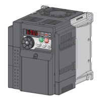
How to solve Mitsubishi Electric FR-D720 K stall prevention (overvoltage)?
- AAshley RuizAug 27, 2025
During deceleration, stall prevention (overvoltage) happens if the regenerative energy of the motor becomes excessive. To prevent overvoltage trip, increase the deceleration time using Pr. 8 Deceleration time.