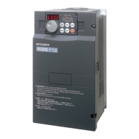
Do you have a question about the Mitsubishi Electric FR-F700 and is the answer not in the manual?
| Brand | Mitsubishi Electric |
|---|---|
| Model | FR-F700 |
| Category | Inverter |
| Language | English |
Enhances energy savings during acceleration/deceleration and constant speed operation.
Confirms energy savings via operation panel, output terminals, and networks with a new monitor.
Allows setting optimal torque patterns for machine characteristics.
Improves energy savings in low speed, offers automatic switchover and monitoring.
Allows operation to continue without motor coasting during fan/blower applications.
Enables restarting the motor without stopping when it's coasting due to power failure.
Smoothly restarts a motor rotating in the opposite direction due to windmill effect.
Avoids overvoltage alarms by automatically increasing frequency.
Allows direct input of motor's built-in PTC for enhanced motor protection.
Simplifies switchover to commercial power using dedicated control circuit terminals.
Features long-life cooling fans and capacitors designed for extended operation.
Diagnoses deterioration of main/control circuit capacitors and cooling fan for proactive maintenance.
Provides timer output to indicate maintenance needs for peripheral equipment.
Facilitates easy updates for inverter firmware and parameters.
Simplifies fan replacement and wiring with user-friendly design features.
Reduces inverter noise with new technologies and a built-in EMC filter for compliance.
Enables connection to high power factor converters for effective harmonic suppression.
Restricts current at power-on using a built-in inrush current limit circuit.
Easy operation with a popular setting dial for quick and accurate frequency and parameter adjustments.
Simplifies inverter setup and maintenance from startup to maintenance tasks.
Includes RS-485 terminals for communication, supporting Modbus-RTU protocol.
Supports connection with major networks like LONWORKS, CC-Link, DeviceNet, and Profibus-DP.
Complies with international safety standards including UL, cUL, and EN (LVD).
Allows utilization of inverter output signals instead of PLC remote output function.
Features standard 12 contact inputs, 3 analog inputs, 5 open collector outputs, etc.
Enables high torque in low-speed regions with simple magnetic flux vector control.
Specifies requirements for the AC power supply to be used within inverter specifications.
Details selection of circuit breakers and fuses for protection against in-rush current.
Advises on safety installation of magnetic contactors, not for frequent start/stop.
Recommends reactors for power harmonics measures, power factor improvement, or large power systems.
Filters to reduce electromagnetic noise generated from the inverter, effective from 1MHz to 10MHz.
Options for increasing braking capability, used with electrical-discharge resistors.
Used in combination with brake units to fully exhibit regenerative braking.
Suppresses power supply harmonics and reshapes current waveform into a sine wave.
Returns braking energy to the power supply, enabling common converter system operation.
Used for connecting computers such as PLCs for control and communication.
Details inverter installation considerations like ambient temperature and wiring practices.
Provides terminals for connecting computers like PLCs, supporting Modbus-RTU.
Notes on devices connected to the output side, like capacitors or surge suppressors.
Emphasizes the importance of grounding the motor and inverter for electric shock prevention.
Explains how inverters reduce wasted power by minimizing losses and motor output, especially for fans and pumps.
Provides outline and mounting dimensions for FR-F720-0.75K and 1.5K inverter models.
Details dimensions for FR-F720 and FR-F740 series inverters from 2.2K to 5.5K capacities.
Presents outline and mounting dimensions for FR-F720/F740 series inverters, 7.5K to 18.5K.
Displays dimensions for FR-F720 (18.5K, 22K, 30K) and FR-F740 (22K, 30K) inverter models.
Provides outline and mounting dimensions for FR-F720/F740 series inverters, 37K to 55K capacities.
Details outline and mounting dimensions for FR-F740-75K and 90K inverter models.
Presents outline and mounting dimensions for the FR-F740-110K inverter model.
Details dimensions for FR-F720 (75K-110K) and FR-F740 (132K, 160K) inverter models.
Provides outline and mounting dimensions for FR-F740 series inverters, 185K to 355K capacities.
Details outline and mounting dimensions for the FR-F740-400K inverter model.
Presents outline and mounting dimensions for the FR-F740-450K inverter model.
Provides outline and mounting dimensions for FR-F740-500K and 560K inverter models.
Shows outline and panel cutting dimensions for the FR-DU07 operation panel.
Details outline and panel cutting dimensions for the FR-PU04 parameter unit.
Illustrates connections for power input and inverter output terminals.
Shows wiring for control input signals, output signals, and auxiliary inputs.
Depicts connections for analog and digital frequency setting signals.
Illustrates connections for PU connector and RS-485 terminals for communication.
Explains the function and connection of main circuit terminals (AC power, inverter output, brake unit, DC reactor).
Details the function and specification of various control circuit input terminals.
Explains analog input specifications for frequency setting and auxiliary inputs.
Explains the use of 24VDC power supply and contact input common terminals.
Details the function and specification of various output signals.
Explains communication specifications for PU connector and RS-485 terminals.
Describes indications for operation mode (PU, EXT, NET) and unit (Hz, A, V).
Explains the function of the 4-digit LED display, monitor indication, and rotation direction indicators.
Details the function of the setting dial, mode switchover key, and operation mode switchover.
Illustrates how to switch between external, PU, and Jog operation modes.
Shows how to monitor output frequency, current, and voltage, and change frequency settings.
Demonstrates how to enter parameter setting mode, change values, and write parameters.
Explains how to display and clear alarm history logs.
Lists basic parameters available in simple mode, including torque boost, frequency limits, and acceleration times.
Lists advanced parameters for functions like DC injection brake, jog operation, and thermal overload relay.
Covers parameters for torque boost, frequency limits, base frequency, and acceleration/deceleration times.
Lists parameters for setting jog frequency and acceleration/deceleration times.
Details parameters for DC injection brake operation frequency, time, and voltage for stopping control.
Includes parameters for acceleration/deceleration reference frequency and time increments.
Covers parameters for stall prevention operation level and compensation factors.
Parameters for configuring multi-speed settings and input compensation.
Parameters related to output frequency detection and detection for reverse rotation.
Parameters for second acceleration/deceleration times, torque boost, and V/F settings.
Parameters for selecting display data, FM/AM terminal functions, and monitoring references.
Covers parameters for automatic restart selection, cushion times, and stall prevention levels.
Parameters for output current detection level, zero current detection, and signal retention time.
Parameters for managing user groups, registration, and display/clear functions.
Assigns functions to input terminals for various operations like start, stop, and selection.
Assigns functions to output terminals for status indications like running, overload, and frequency detection.
Parameters for configuring multi-speed settings from 8 to 15 speeds.
Parameters for rated slip, slip compensation time, and constant-output region slip selection.
Parameters for soft-PWM operation, analog input switchover, and compensation amounts.
Parameters for monitoring the life status of internal components like capacitors and fans.
Parameters to control inverter behavior during power failure, including stop selection and deceleration times.
Settings for RS-485 communication, including station number, speed, parity, and error retries.
Parameters for configuring remote output selection and data output.
Parameters for setting maintenance timers and alarm output times.
Parameters for monitoring average output current and setting output references.
Parameters for PID control, including proportional band, integral time, and limits.
Parameters to manage regeneration avoidance operation, levels, and voltage gain.
Parameters for monitoring energy saving effects, load factor, and power saving calculations.
User-definable parameters for custom applications or tracking.
Parameters for calibrating FM and AM terminals for accurate analog signal measurement.
Functions for clearing parameters, alarm history, and copying settings between inverters.
Explains parameters for compensating voltage drop to improve motor torque in low-frequency regions.
Details how to select preset speeds using contact signals and configure multi-speed settings.
Explains parameters for limiting motor speed by setting upper and lower output frequency limits.
Covers parameters for adjusting inverter output (voltage, frequency) to motor ratings and for multi-motor setups.
Explains parameters for setting acceleration and deceleration times, including increments and reference frequencies.
Details parameters for setting overcurrent protection to prevent motor overheat.
Explains parameters for DC injection brake operation frequency, time, and voltage for stopping control.
Describes parameters for selecting optimal V/F characteristics based on application and load types.
Covers parameters for setting jog frequency and acceleration/deceleration times for precise positioning.
Explains how to select the logic for the MRS signal to shut off inverter output.
Parameters to set starting frequency and hold time for smoother motor starts.
Details parameters for preventing inverter alarms due to overcurrent or overvoltage during operation.
Explains multi-speed settings from 4 to 15 speeds and their configuration.
Covers parameter for compensating speed based on input signals for multi-speed or remote settings.
Explains parameters for setting acceleration/deceleration patterns and backlash measures.
Details options for selecting regeneration units like brake units or high power factor converters.
Explains parameters for setting frequency jump points to avoid mechanical resonance.
Covers parameters for detecting output frequency and triggering output signals.
Explains how to change the display and setting between motor speed and machine speed.
Covers parameters for selecting monitor displays and clearing cumulative data.
Explains parameters for setting the full-scale value for outputting frequency and current monitor values.
Details parameters for restarting the inverter after power failure or for flying start operations.
Explains how to use contact signals for continuous variable-speed operation and remote settings.
Covers parameters for automatic energy saving operation, including normal and optimum excitation control modes.
Explains parameters for automatic inverter restart after alarms and retry settings.
Details parameter settings for using constant-torque motors and their thermal characteristics.
Explains parameters for changing carrier frequency and selecting SoftPWM operation for motor sound control.
Covers analog input selection, added compensation, and override functions for speed setting.
Explains parameter for setting the input filter time constant to reduce noise in analog signals.
Covers parameters for reset input acceptance, PU disconnection detection, and PU stop function.
Details parameter for outputting alarm codes as 4-bit digital signals from open collector terminals.
Parameter to prevent accidental rewriting of settings by enabling/disabling parameter write.
Function to prevent reverse rotation faults caused by incorrect start signal input.
Allows selection of operation modes (PU, External, Network) and specifies power-on mode.
Explains simple magnetic flux vector control for high torque in low-speed regions.
Allows creating custom V/F characteristics by setting five frequency/voltage points.
Covers initial settings for RS-485 communication, including station numbers, speed, and protocols.
Details analog input configuration, calibration, and display unit selection.
Explains PID control parameters for process control applications like flow rate or air volume.
Covers parameters for commercial power supply-inverter switchover sequence and selection.
Allows switching the display language of the parameter unit (FR-PU04).
Explains functions for detecting output current and zero current for monitoring purposes.
Details how to select the second function using the RT signal and set its action conditions.
Covers restricting parameter display and using the user group function for custom settings.
Explains how to use the operation panel's setting dial and disable key operations.
Details how to assign functions to open collector and relay output terminals.
Explains how to assign functions to input terminals for various operations.
Parameters for configuring multi-speed settings from 8 to 15 speeds.
Parameter to select carrier frequency for motor sound and noise reduction.
Covers analog input selection and compensation amount settings.
Explains how to control the cooling fan operation to extend its life.
Covers parameters to enable or disable input/output phase failure protection.
Parameters for slip compensation to maintain motor speed under varying loads.
Explains options for stopping the motor (coasting/deceleration) and start signal operations.
Details parameters for monitoring and diagnosing the life status of inverter components.
Covers parameters for inverter behavior during power failures, including stop and restart modes.
Lists parameters related to analog input selection, monitor digits, rotation detection, and RS-485 communication.
Explains parameters to automatically increase frequency and avoid regeneration status.
Details parameters for monitoring energy saving effects, load factor, and power saving calculations.
Covers parameter for enabling or disabling the buzzer on the operation panel and parameter unit.
Allows adjustment of the LCD contrast for the parameter unit (FR-PU04).
Explains calibration procedures for FM and AM analog output terminals.
Details functions for clearing parameters, alarm history, and copying settings between inverters.
Lists error messages displayed on the PU for inverter faults and protective actions.
Describes warnings indicating potential issues before major failures occur.
Lists minor faults that provide output signals indicating operational status.
Details major failures that activate protective functions and stop the inverter output.
Continues the list of major failures, including CPU errors, power supply issues, and communication errors.
Lists plug-in options like digital input, analog output, and relay outputs.
Describes shared options like communication units, parameter units, and attachments.
Discusses sine wave filters for noise reduction and surge voltage suppression.
Lists manual and speed controllers for various operation modes like independent, synchronous, and remote.
Includes calibration resistors and software for inverter setup and maintenance.
Attachments for replacing older FR series inverters with the FR-F700 series.
Reactors for harmonic current reduction and power factor improvement on the AC side.
Reactors for harmonic current reduction and power factor improvement on the DC side.
Filters to reduce line noise, with different models for small capacities.
Options to enhance regenerative braking capability, used together with resistors.
Provides a table for selecting brake units based on motor capacity and required braking torque.
Lists combinations of brake units, resistor types, and required cable sizes for connection.
Details brake unit selection for 400V class inverters based on motor capacity and braking torque.
Lists brake and resistor unit combinations and cable specifications for 400V class inverters.
Discusses torque characteristics, loss, vibration, and temperature rise when using standard motors with the inverter.
Explains how motor operating torque and temperature rise are affected by inverter use, especially at low speeds.
Addresses potential limitations in motor torque (especially starting torque) compared to commercial power supply operation.
Discusses causes of potential vibration increases with inverter-operated motors and frequency jump function.
Provides guidance on selecting inverter capacity and torque boost settings for constant-torque motors.
Offers considerations for using special motors like pole changing, geared, or synchronous types.
Provides measures to mitigate surge voltages and protect motor insulation for 400V class motors.
Recommends optional filters (FR-ASF-H, MT-BSL/BSC) to suppress surge voltages on the inverter output.
Highlights differences in simple mode parameters, especially Pr.0 Torque Boost initial values.
Lists functions that were changed or cleared between FR-F500(L) and FR-F700 series.
Notes the removability and compatibility of terminal blocks between series.
Compares PU unit compatibility and availability between the two series.
Compares plug-in options like computer link and relay output units.
Discusses installation size compatibility and the need for intercompatibility attachments.
Outlines the warranty period, scope of coverage, and failure diagnosis process.
Specifies that consequential losses and damages to other products are not covered under warranty.
States the duration for which Mitsubishi will accept product repairs after production ceases.
Clarifies that standard products are delivered without application settings and Mitsubishi is not liable for on-site adjustments.
Provides contact information for Mitsubishi Electric Automation in North America.
Lists contact details for Setsuyo Enterprise Co., Ltd. in Taiwan.
Provides contact information for Mitsubishi Electric Automation Korea Co., Ltd.
Lists contact details for Mitsubishi Electric Automation (Shanghai) Ltd. Beijing Office.
Provides contact information for Mitsubishi Electric Automation (Shanghai) Ltd. Tianjin Office.
Lists contact details for Mitsubishi Electric Automation (Shanghai) Ltd. in Shanghai.
Provides contact information for Mitsubishi Electric Asia Pte, Ltd. in Singapore.
Lists contact details for Mitsubishi Electric Automation (Hong Kong) Ltd.
Provides contact information for Mitsubishi Electric Europe B.V. German Branch.
Lists contact details for Mitsubishi Electric Europe, B.V. UK Branch.



 Loading...