Control circuit Installation and wiring
2 - 64
2.6.7 Safety stop function
Function description
The terminals related to the safety stop function are shown below.
In the initial status, terminals S1 and PC, S2 and PC, and SIC and SD are respectively shorted with
shorting wires. To use the safety stop function, remove all the shortening wires, and then connect
to the safety relay module as shown in the following connection diagram.
At an internal safety circuit failure, the operation panel displays one of the faults shown on page 2-65.
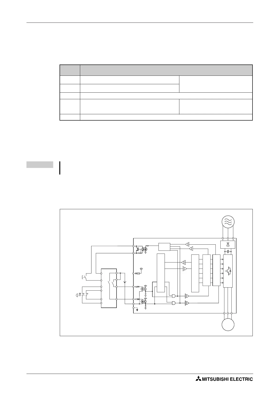
Connection diagram
To prevent automatic restart after a fault occurrence, connect the reset button of a safety relay mod-
ule or a safety programmable controller across the terminals SO and SOC. The reset button acts as the
feedback input for the safety relay module or the safety programmable controller.
Ter mi na l
symbol
Terminal function description
S1
For input of the safety stop channel 1.
Between S1 and SIC, S2 and SIC
Open: In safety stop mode
Short: Other than the safety stop mode.
S2
For input of the safety stop channel 2.
SIC
Common terminal for S1 and S2.
SO
Outputs when an alarm or failure is detected.
The signal is output when no internal safety circuit failure
exists.
OFF: Internal safety circuit failure
ON: No internal safety circuit failure
SOC Open collector output (terminal SO) common
Tab. 2-26: Safety stop signal
NOTE Use the terminal SO to output a fault and to prevent restarting of the inverter. The signal cannot
be used as safety stop input terminal to other devices.
I003010E
Fig. 2-44: Connecting the Safety relay module
R/L1
S/L2
T/L3
U
V
W
SO
SOC
S1
S2
G G
SIC
SD
PC
+24V
RESET
Logic
CPU
Fuse
ASIC
Gate Driver
Gate Driver
IGBTs
Emergency
stop button
Safety relay module/
Safety programmable controller
24 V DC
M
Inverter
 Loading...