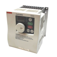
Why Mitsubishi Electric FR-S520E Inverter motor current is large?
- KkathrynsantosAug 17, 2025
If the motor current is large, verify that the load isn't too heavy and that the torque boost setting isn't excessively high.

Why Mitsubishi Electric FR-S520E Inverter motor current is large?
If the motor current is large, verify that the load isn't too heavy and that the torque boost setting isn't excessively high.
What to do if Mitsubishi Electric FR-S520E Inverter speed greatly differs from setting?
If the speed greatly differs from the setting, check that the frequency setting signal is correct, confirm that the following parameter settings are correct: Pr. 38, Pr. 39, Pr. 95, C2 to C7, and ensure that the input signal lines are not affected by noise.
Why Mitsubishi Electric Inverter speed varies during operation?
If the speed varies during operation, verify that the load isn't varying, the frequency setting signal isn't varying or affected by noise, the wiring length isn't too long, and the GD[2] load isn't small (at the motor GD[2] or smaller).
How to fix Mitsubishi Electric FR-S520E motor remains stopped?
To address a motor that remains stopped: * Ensure the motor is properly connected. * Verify the main circuit display is provided. * Confirm the jumper across P-P1 is connected. * Check the start signal is input and the frequency setting signal is not zero. * Ensure the operation mode (Pr. 79) setting is correct and the starting frequency (Pr. 13) setting is not greater than the running frequency. * Check that the load is not too heavy and the shaft is not locked.
What causes Mitsubishi Electric Inverter acceleration/deceleration is not smooth?
If the acceleration or deceleration is not smooth, check that the acceleration and deceleration time setting is correct, the load is not too heavy and the torque boost setting is not too large.
Why Mitsubishi Electric FR-S520E motor rotates in opposite direction?
If the motor rotates in the opposite direction, check that the phase sequence of output terminals is correct, the start signals (forward rotation, reverse rotation) are setup properly, and the setting of Pr. 17 "RUN key rotation direction".
Why Mitsubishi Electric Inverter speed does not increase?
If the speed does not increase, check that the maximum frequency setting is correct and that the load is not too heavy.
What to do if Mitsubishi Electric FR-S520E operation mode is not changed properly?
If the operation mode is not changed properly, verify that the STF or STR signal is off and check the Pr. 79 setting.
How to solve Mitsubishi Electric FR-S520E Inverter parameter write cannot be performed?
If a parameter write cannot be performed, make sure that operation is not being performed (signaled), check that the SET (WRITE) was pressed, and ensure that you are not attempting to set the parameter range or the operation mode.
What to check if Mitsubishi Electric Inverter motor produces annoying sound?
If the motor produces an annoying sound, check the Pr. 70 "Soft-PWM setting" and Pr. settings.
| Series | FR-S520E |
|---|---|
| Output Frequency | 0.5 to 400 Hz |
| Cooling Method | Fan cooled |
| Input Voltage | 200-240 VAC |
| Input Phase | Single-phase/Three-phase |
| Control Method | V/F Control |
| Overload Capacity | 150% for 60 seconds |
| Protection Features | Overcurrent, Overvoltage, Undervoltage, Overheating, Short Circuit |
| Communication | RS-485 |
| Operating Temperature | -10 to +50 °C |
| Storage Temperature | -20 to +65 °C |
| Humidity | 95% RH or less (non-condensing) |
| Altitude | 1000 m or less |
| Enclosure Rating | IP20 |
Details the standard connection diagram and specifications for main and control terminals.
Explains the layout and connection of main circuit terminals for various inverter models and power inputs.
Guides on using the control circuit terminals, including wiring and logic changes.
Describes various input terminals like start/stop, frequency setting, and multi-speed selection.
Explains how to use specific input signals assigned to terminals like RL, RM, RH, and STR.
Details connections for optional units like brake resistors, brake units, and converters.
Covers connection and communication using the RS-485 connector for parameter units.
Provides general design considerations and safety interlocks for system integration.
Provides a comprehensive list of all parameters with their settings, ranges, and reference pages.
Organizes parameters by their function and application for easier selection and configuration.
Details the purpose, settings, and related parameters for each function/parameter.
Lists and explains various error codes, their causes, and corrective actions for inverter protection.
Provides guidance on diagnosing and resolving common operational issues and faults.
Outlines safety precautions and procedures for routine maintenance and inspection of the inverter.
Details technical specifications including ratings, power supply, cooling, and approximate mass for various models.
Provides outline dimension drawings and mounting hole details for different inverter capacities.
 Loading...