HEAD OFFICE: TOKYO BUILDING 2-7-3, MARUNOUCHI, CHIYODA-KU, TOKYO 100-8310, JAPAN
3
4
5
6
7
1
2
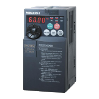
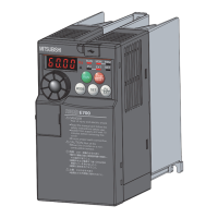
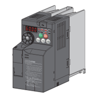
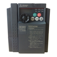
FR-E700
INSTRUCTION MANUAL (Applied)
INVERTER
PRECAUTIONS FOR USE
OF THE INVERTER
PARAMETERS
TROUBLESHOOTING
PRECAUTIONS FOR
MAINTENANCE AND INSPECTION
SPECIFICATIONS
OUTLINE
WIRING
MODEL
MODEL
CODE
1A2-P26
FR-E700
INSTRUCTION MANUAL (Applied)
FR-E720-0.1K(SC) to 15K(SC)
FR-E740-0.4K(SC) to 15K(SC)
FR-E720S-0.1K(SC) to 2.2K(SC)
FR-E710W-0.1K to 0.75K
IB(NA)-0600277ENG-F (1009)MEE Printed in Japan Specifications subject to change without notice.
INVERTER FR-E700 INSTRUCTION MANUAL (Applied)
F