EasyManua.ls Logo

Mitsubishi Electric FR-V560 User Manual

Mitsubishi Electric FR-V560
243 pages
To Next Page IconTo Next Page
Page #1 background imageLoading...
Page #1 background image
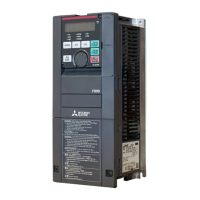
VECTOR INVERTER
FR-V560
INSTRUCTION MANUAL (Detailed)
IB(NA)-0600135E-A(0306)MEE Printed in Japan Specifications subject to change without notice.
2
VECTOR CONTROL
WITH ENCODER
PARAMETERS
4
SPEC IFICATIONS
6
HEAD OFFICE:MITSUBISHI DENKI BLDG MARUNOUCHI TOKYO 100-8310
3
VECTOR CONTROL
WITHOUT ENCODER
1
WIRING
PROTECTIVE
FUNCTIONS
5
FR-V560-NA
VECTOR INVERTER INSTRUCTION MANUAL (Detailed)
FR-V560-2.2K to 55K-NA
HIGH PRECISION & HIGH
RESPONSE VECTOR INVERTER

Table of Contents

Questions and Answers:

Mitsubishi Electric FR-V560 Specifications

General IconGeneral
ModelFR-V560
SeriesFR-V500
Frequency Range0.5Hz to 400Hz
Cooling MethodForced air cooling
Operating Temperature-10°C to +50°C
Storage Temperature-20°C to +65°C
Enclosure RatingIP20
Input Voltage3-phase 380 to 480 V AC, 50/60 Hz
Control MethodVector control
Protection FeaturesOvercurrent, Overvoltage, Undervoltage, Overheat, Ground fault
Communication InterfacesRS-485
Humidity5% to 95% RH (non-condensing)
AltitudeUp to 1000m above sea level

Summary

WIRING

Basic configuration and connection of peripheral devices

Explains fundamental setup and connection of devices like power supply, breakers, and motors.

Connection diagram

Provides detailed wiring diagrams for main and control circuits, including motor and encoder connections.

Control circuit terminal specifications

Details the specifications and functions of control circuit terminals for input, output, and communication.

Precautions for use of the vector inverter

Outlines critical safety and handling precautions to prevent damage or injury during inverter use.

Input terminals

Describes the functions and connections of various input terminals for start, stop, and speed/torque commands.

How to use the input signals (assigned terminals DI1 to DI4, STR) (Pr. 180 to Pr. 183, Pr. 187)

Explains how to assign functions to digital input terminals for various operations like multi-speed and jog.

VECTOR CONTROL WITH ENCODER

What is vector control?

Introduces the principles of vector control for induction motors, including equivalent circuits and advantages.

Speed control

Details how to perform speed control using the inverter, including basic outlines and gain tuning.

Fine adjustment of gains for speed control

Provides methods for fine-tuning speed control gains to optimize performance and resolve issues like vibration.

Position control (Pr. 419 to Pr. 430, Pr. 464 to Pr. 494)

Explains how to configure and use the position control functions for precise motor shaft positioning.

VECTOR CONTROL WITHOUT ENCODER

Speed control (without encoder)

Describes the basic speed control methods when an encoder is not used.

Fine adjustment of gains for speed control (without encoder)

Details procedures for adjusting speed control gains to optimize performance and resolve issues without an encoder.

Torque control (without encoder)

Explains the principles and setup for torque control when an encoder is not used.

Gain adjustment for torque control (without encoder)

Provides guidance on manually adjusting torque control gains to resolve vibration or overcurrent issues.

PARAMETERS

Parameter lists

Provides a comprehensive list of all inverter parameters, their factory settings, and ranges for reference.

Basic functions (Pr. 0 to Pr. 9)

Covers fundamental parameters like torque boost, speed limits, and acceleration/deceleration times.

Operation selection functions 1 (Pr. 17 to Pr. 37)

Details parameters for selecting various operational modes like jog, stop, and torque restriction.

Operation selection function 2 (Pr. 65 to Pr. 79)

Explains parameters for retry functions, motor selection, PWM frequency, and speed setting signals.

PID control (Pr. 128 to Pr. 134)

Describes the configuration and adjustment of PID control for process regulation, including action types.

Terminal assignment functions (Pr. 180 to Pr. 195)

Explains how to assign functions to input and output terminals for flexible control.

Orientation (Pr. 350 to Pr. 362, Pr. 393 to Pr. 399)

Covers functions for motor shaft positioning using encoder feedback and associated parameters.

Operation selection functions 4 (Pr. 800 to Pr. 809)

Covers parameters for selecting control methods, torque characteristics, and speed restrictions.

Control system functions (Pr. 818 to Pr. 837)

Details parameters for tuning control systems, including easy gain tuning and speed/torque filters.

Protective functions (Pr. 870 to Pr. 874)

Details protective functions like speed deviation, speed restriction, and OLT level prevention.

PROTECTIVE FUNCTIONS

Errors (Alarms)

Lists and explains various error codes and alarms, including major faults and minor faults with corrective actions.

Resetting the inverter

Explains the procedures for resetting the inverter after faults or parameter changes to resume operation.

SPECIFICATIONS

Model specifications

Lists the technical specifications for different inverter models, including ratings and capacities.

Common specifications

Details common specifications applicable to all inverter models, such as control systems and environmental conditions.

Outline dimension drawings

Provides physical dimensions and mounting hole information for inverter units and operation panels.

Related product manuals