Do you have a question about the Mitsubishi Electric Freqrol FR-U120S-EC and is the answer not in the manual?
| Overload Capacity | 150% for 60 seconds |
|---|---|
| Operating Temperature | -10 to +50 °C |
| Storage Temperature | -20 to +65 °C |
| Enclosure Rating | IP20 |
| Series | FR-U |
| Output Voltage | 200-240V AC |
| Frequency Range | 0.5 to 400 Hz |
| Control Method | V/F control |
| Protection Functions | Overcurrent, overvoltage, undervoltage, overheat |
| Braking Unit | Built-in |
| Communication | RS-485 |
| Cooling Method | Forced air cooling |
| Ambient Humidity | Less than 95% RH (non-condensing) |
| Altitude | Up to 1000 m |
Safety measures to prevent electric shock during operation, wiring, and inspection.
Precautions to prevent fire hazards, including mounting and power supply considerations.
Guidelines to prevent injury, such as correct voltage application and handling hot components.
General safety instructions for transportation, installation, wiring, operation, emergency stop, maintenance, disposal, and general use.
Explanation of EMC Directive compliance, including view of inverters and installation requirements.
Information regarding the Low Voltage Directive, compliance with standards, and instructions.
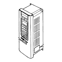
Identification of key components like the key pad, model plate, and rating plate.
Details of terminal blocks for control circuits (TB1, TB2) and power supply/motor connections.
Instructions on how to remove and mount the front cover of the inverter.
Recommendations for vertical installation, ambient temperature, and avoiding unsuitable locations.
Essential precautions and planning details for safe and correct inverter wiring.
Diagram and instructions for connecting the power supply and motor to the inverter.
Details on connecting control signals to terminal blocks TB1 and TB2.
Specifications for wire size and sheath peeling length for terminal connections.
Overview of different operation methods: key pad, external input signal, and combined use.
Detailed guide on operating the inverter using the key pad interface.
Instructions for operating the inverter using external switches and signals.
Explanation of key pad buttons, display, and adjusting parameter settings.
A comprehensive table listing all inverter functions with their parameter numbers and setting ranges.
In-depth explanations of various inverter functions, covering operation, settings, and parameters.
Key standard specifications for the inverter, including power, voltage, and capacity ratings.
Common technical specifications covering control, input signals, output signals, and environmental conditions.
Diagram illustrating the terminal connections for main and control circuits of the inverter.
Detailed explanation of each terminal's symbol, name, and function.
Description of the built-in protective functions of the inverter, including overcurrent and overload protection.
Dimensional drawings and mounting hole details for FR-U120S-N-EC 0.2 to 0.4K models.
Dimensional drawings and mounting hole details for FR-U120S-N-EC 0.75K models.
Guidelines for selecting appropriate peripheral devices like NFB, contactors, and wiring based on motor output.
Information on mains conducted emissions filters, including specifications and dimensions.
Details on warranty exclusions, including opportunity losses and repair policies.
Important notes on the product's intended use, limitations, and specific application considerations.
Instructions and diagram for connecting the motor earth to the inverter's cabinet.